Quantcast
Channel: arduino – Tinkerman
Viewing all 26 articles
Browse latest View live

Smartmeter pulse counter (2)

$
0
0

This week I have had some spare time – well, I should say I’ve borrowed some time from my sleep – to work on the smart-meter pulse counter setup.

In my last post about this I analized the signal from my photocell sensor. My conclusion was that the signal was clean and neat, even before throwing in a schmitt trigger to make it more “digital”. I have found out that it is also very dependent on the environmental light so I good isolation is a must for the sensor.

I had already prepared a sensor probe with a 3.5mm audio jack on one end and the photocell on the other. But the photocell is aligned with the cable, which is quite rigid and I am concerned about how to attach it to the smart meter case. For now I will leave it like that and do some real scenario tests. Since it is an external sensor I can change it whenever I want.

Finally I have also added an RC filter to the sensor input. The previous data suggests it is not necessary but I needed to do some tests with a faked signal source (a mini button) and it won’t harm.

Aside from these things I’ve done some very important steps forward. I have a final schema for the board.

There are some points worth noticing:

  • I’ve added a ceramic capacitor across VDD and GND as the Xbee documentation recommends. I didn’t have the 1uF and 8.2pF ones but I have seen some boards with the *standard* 100nF.
  • There is a voltage divider for the battery monitoring on the top right corner.
  • On the bottom you can see the voltage divider with the photocell in series with the RC filter
  • I’m wiring DIO9 *and* DTR to the Arduino, this way I can switch from Xbee-driven to Arduino-driven from code (more on this later).
  • Finally I decided to wire DOUT to the Arduino (I’m using SoftwareSerial, so RX and TX pins are digital 5 and 6 respectively) Not any more. I am using hardware serial on the final version…

This setup allows me to choose between two very different approaches: I can make Arduino drive the sleep cycle by changing DTR pin (Xbee in mode SM1 or “pin sleep”) or I can make the Xbee control the sleep cycle (Xbee in mode SM4/5 or “cycle sleep”) triggering an Arduino interrupt  when it awakes.

The first option lets me send a report every N pulses. In my case 4 pulses equal 1Wh. Lets say I want to report chunks of 5Wh, that’s 20 pulses. That means a report every 4.5 to 90 seconds depending on the current load (200W to 4kW range), being 60 seconds (300W) the average.

With the second option I can report average power consumption every minute. The Arduino counts the pulses and when the Xbee awakes it asks the Arduino (i.e. triggers an interrupt) to calculate and report the average power consumption over the last minute. For instance, if the pulse count is 28, that’s 7Wh over the last minute or an average of 420W.

I prefer the later because the reports are evenly spaced which means they are somewhat easier to graph and the graph is more meaningful: if you graph the power in the Y axis and time in the X axis the area below the power line is the energy (watts * hour). With the former the data should be post-processed to get some useful information like average Wh per day.

I’ve already done some tests but, so far, I have not been able to program the Xbee to follow an accurate sleep cycle. To configure the sleep period you can use SP and SN, the first one represents the time in tens of milliseconds, the second is a multiplier. So with SP=0x03E8 (1000 in hex) and SN=0×06 that’s 60 seconds. The problem is that the awake period has it’s own counter, ST, which is reset “each time serial or RF data is received”. That introduces a random time in the calculation which translates into a slight shift in the reports.

Option B would be to use some RTC to awake the Xbee with an alarm trigger. But I would rather avoid adding more hardware to the sensor.

Well, still a lot of things to figure out… more to follow :)


Smartmeter pulse counter (4)

$
0
0

This is going to be the last post for the smart meter pulse counter setup series. I want to wrap up several things like the final hardware, the code and the data visualization.

Final hardware

This is what the pulse counter sensor looks like, almost. The final version that’s already “in production” has a switch to hard-reset the radio from outside the enclosure. Nothing special otherwise. Everything goes in a socket so I could reuse the components, the photocell probe connects to the 3.5mm jack that’s on the top of the box and I’m using 3 alkaline AA batteries (not the rechargeable ones in the picture).

Code

The code is freely available under GPLv3 license on github. The code itself is pretty simple: it uses the Arduino LowPower library by RocketScream to keep the arduino sleeping for most of the time. It only wakes on an event on any of the two possible interrupt pins:

void setup() {

pinMode(LDR_INTERRUPT_PIN, INPUT);
pinMode(XBEE_INTERRUPT_PIN, INPUT);
pinMode(XBEE_SLEEP_PIN, OUTPUT);

Serial.begin(9600);

// Using the ADC against internal 1V1 reference for battery monitoring
analogReference(INTERNAL);

// Send welcome message
sendStatus();

// Allow pulse to trigger interrupt on rising
attachInterrupt(LDR_INTERRUPT, pulse, RISING);

// Enable interrupt on xbee awaking
attachInterrupt(XBEE_INTERRUPT, xbee_awake, FALLING);

}

The LDR_INTERRUPT pin is there the photocell based voltage divider is plugged to. When the photocell resistance drops due to a light pulse the pin sees a RISING transition and the Arduino counts the pulse. The XBEE_INTERRUPT pin is connected to the ON_SLEEP pin of the XBee (pin 13). When the XBee is sleeping this pin is pulled high and when it awakes the pin goes low and the Arduino sends the message.

void pulse() {
  ++pulses;
}
void xbee_awake() {
  ready_to_send = true;
}

On the main loop the arduino sleeps until an event awakes it. If the event has been triggered by the XBee then it calls the message sending methods.

void loop() {

// Enter power down state with ADC and BOD module disabled
LowPower.powerDown(SLEEP_FOREVER, ADC_OFF, BOD_OFF);

// Check if I have to send a report
if (ready_to_send) {
ready_to_send = false;
sendAll();
}

}

Results

The messages are being received by an XBee coordinator radio that’s connected to an USB port in my home server. On the server my xbee2mqtt daemon is running listening to incoming messages from the radio port. The messages are mapped to MQTT topics (namely /benavent/general/power and /benavent/powermeter/sensor/battery).

The the mqtt2cosm mqtt2cloud daemon (I will write a post about this one soon) pushes the data to Cosm.com or Tempo-db.com. And the final result looks like this:

First issues

The pulse counter has been running for some days now and the first issue has arised. You may notice in the previous graph that from time to time the sensor stops reporting data for several minutes. I still have to find out what’s going wrong but my guess is that there is some issue with the interrupts and the transmissions. I am not disabling interrupts while transmitting because I thought it was not necessary when using the hardware UART, but maybe I was wrong.

The problem doesn’t seem to be related to the time of day, the power measure and in the tests I did while testing the XBee sleep cycle it did not happen (the probe was not plugged in so there were no additional interrupts…). The distance to the coordinator radio was one of the problem generation candidates in my first tests but now I am testing another sensor that’s just one meter apart from the pulse counter and it reports flawlessly…

Any suggestions?

Decoding 433MHz RF data from wireless switches

$
0
0

[Update 2013-03-01] I have added more documentation on the codes these remotes use in a different post.

I’m starting to move towards not only gathering information but also acting. My first project in this subject will be controlling some lights and the house heaters. So last week I visited the urban market of “Els Encants” in Barcelona and bought some very cheap wireless outlets.

I bought two sets of three wall plugs, each set with it’s own remote. They all transmit in the  433MHz frequency and I already had a set of transmitter and receiver for that frequency so as soon as I had some time I started trying to intercept and reproduce the codes the remotes were sending.

Sample outlets from each set plus remotes

Sample outlets from each set plus remotes

In the image above you can see an outlet and the remote for each of the sets. The left one is branded “Noru” and each outlet is rated 3kW (good for the heaters) and it features auto switch off time (1, 2, 4 or 8 hours). The remote can control a maximum of 3 outlets and apparently it is programmable, since you first have to sync the outlets with the remote.

The right one is branded “Avidsen” and rated 1000W, just below the consumption of my house electrical heaters, but good to control lights and other appliances. It’s got the very common dip switch to sync the remote and up to five outlets. There are 32 different channels available. So if your lights switch on and off randomly maybe you neighbour is using the same channel you are, then you better change the channel.

I started reading documentation about the protocol these devices use and found out there is some very useful information out there. In fact there are even a couple of libraries for Arduino. The first one is called RemoteSwitch and it is a little old, it has not been ported to Arduino 1.0 but if you are like me you will keep a copy of Arduino 0023 just for this kind of situations.

The second library is called RCSwitch and I have to say it is a neat piece of code. It has been ported to the Raspberry Pi, although the port is not as updated as the original Arduino library.

My first tests with the RemoteSwitch library were encouraging. The Show_received_code sketch dumped the codes for the Avidsen remote one by one. I though: if it can decode it, it should be able to recreate it. And it worked from scratch. Good!

But by then I knew I wanted to use the newer library. There were several reason for this: it is being actively developed, it supports more protocols, the code is much more elegant and object oriented and it has a port to RPi, which I plan to use as a central gateway soon. So I checked which one of the RCSwitch protocols matched the one I had successfully used with RemoteSwitch and started doing some more tests…

Here was when things started to get complicated. The thing did not work. So I spent a couple of hours studying the code for both libraries, decoding the codes the RemoteSwitch library had dumped before and trying to find the difference. Until I found it: RCSwitch.cpp, line 239, that ’0′ should be a ’1′… and everything started working again. Very good! I started a thread in the library forum to find out whether this is a bug or a slightly different protocol.

Index: RCSwitch.cpp
===================================================================
--- RCSwitch.cpp	(revision 219)
+++ RCSwitch.cpp	(working copy)
@@ -284,7 +284,7 @@
         if (sGroup[i] == '0') {
             sDipSwitches[j++] = 'F';
         } else {
-            sDipSwitches[j++] = '0';
+            sDipSwitches[j++] = '1';
         }
     }

By the way, the protocol of these things is pretty interesting. It’s worth a look at Sui’s post to get an overview of the implementation. The tri-bit concept is really awkward.

Then I moved to the other set of outlets. These are rated 3000W so I plan to use them to control my house heaters, which is the main reason for all this work. I followed the same steps, starting with getting the codes with the Show_received_code sketch. But weird enough the library was only able to decode some of the button presses… Only the SET button for outlet #1, the ON and OFF buttons for outlet #2, the ALL OFF button or the 2, 4 and 8H timeout buttons seemed to work.

This time it was going to be harder, since I didn’t even have all the codes. Well, a good opportunity to use my Bus Pirate!

Bus Pirate to the rescue!

Bus Pirate to the rescue!

So I plugged the RF receiver to the Bus Pirate and launched the OLS Logic Analyser to capture the signal from the remote.

You don’t have to configure anything to use the Bus Pirate as a (low speed) logic analyser. But since I wanted to power the radio receiver with the BP I had to enable the Power Supply mode. To do so you have to open a terminal session, type ‘?’ to get a prompt, select one of the modes that allow enabling the power supply typing ‘m’ and selecting the mode (like UART, for instance) and then type ‘W’ (uppercase to enable, lowercase to disable). Then you can close the session and it will keep the power on the 5V and 3V3 lines as long as it is plugged to the computer. Mind you have to free the port so the logic analyser software can use it. I had problems doing it with screen or minicom, but it worked great with picocom.

After some tests with the Avidsen remote (I knew what the codes were so I could compare the signal output with the actual code) I started getting the signals for each and every button in the Noru remote.

The image below shows the signal for the ON button for the outlet #1.

Signal for the #1 ON button of the Noru remote

Signal for the #1 ON button of the Noru remote

Now, since the RemoteSwitch library was able to decode some of the signals, the protocol could not be that different. So I started to decode manually all the signals applying the same protocol. The signal is a series of 12 tri-bits plus a sync-bit. For the Avidsen-like remotes there are 3 different tri-bit values (logically), they are called 0, 1 and F, for “floating”. Each tri-bit has a pulses shape. The following tables describes the pulses:

Tri-bit Pulses
0 short high + long low + short high + long low
1 long high + short low + long high + short low
F short high + long low + long high + short low

The long pulses are about 3 times the length of the sort ones. The overall period is a characteristic of each remote. There is also a trailing high pulse followed by a long low which is called “sync bit”.

Decoding the signals from the Noru remote I found out that there was a fourth tri-bit value (well maybe I should call them tetra-bits now). In fact it is obvious since there is a forth option for an alternate sequence of 4 highs and lows. I’ve named the new tetra-bit X (for unknown, but also after my name :P ). The full table for the Noru remotes is:

Tretra-bit Pulses
0 short high + long low + short high + long low
1 long high + short low + long high + short low
F short high + long low + long high + short low
X long high + short low + short high + long low

Now the previous image for the ON#1 button can be decoded as 1F000001FFX0S. With a small patch I could make this work with the RCSwitch library. The library cannot create the code but you can feed it to the sendTriState method to generate the signal.

Index: RCSwitch.h
===================================================================
--- RCSwitch.h	(revision 219)
+++ RCSwitch.h	(working copy)
@@ -106,6 +106,7 @@
     void sendT0();
     void sendT1();
     void sendTF();
+    void sendTX();
     void send0();
     void send1();
     void sendSync();
Index: RCSwitch.cpp
===================================================================
--- RCSwitch.cpp	(revision 219)
+++ RCSwitch.cpp	(working copy)
@@ -441,6 +441,9 @@
         case '1':
           this->sendT1();
         break;
+        case 'X':
+          this->sendTX();
+        break;
       }
       i++;
     }
@@ -561,6 +564,16 @@
 void RCSwitch::sendTF() {
   this->transmit(1,3);
   this->transmit(3,1);
+}
+
+/**
+ * Sends a Tri-State "X" Bit
+ *            ___   _
+ * Waveform: |   |_| |___
+ */
+void RCSwitch::sendTX() {
+  this->transmit(3,1);
+  this->transmit(1,3);
 }

 /**

And this is a sample code for Arduino that switches on and off outlet #1 every 2 seconds.

#include <RCSwitch.h>

RCSwitch mySwitch = RCSwitch();

void setup() {

  Serial.begin(9600);

  // Transmitter is connected to Arduino Pin #11
  mySwitch.enableTransmit(11);

  // Optional set pulse length.
  mySwitch.setPulseLength(302);

  // Optional set protocol (default is 1, will work for most outlets)
  mySwitch.setProtocol(1);

  // Optional set number of transmission repetitions.
  mySwitch.setRepeatTransmit(6);

}

void loop() {
    mySwitch.sendTriState("1F000001FFX0");
    delay(2000);
    mySwitch.sendTriState("1F000001FFFX");
    delay(2000);
}

Again, comments are more than welcome!

The Rentalito

$
0
0

“Say Hello to The Rentalito!”

That was the first message The Rentalito displayed almost 2 years ago. The Rentalito means something like “small rental monitoring thingy” (free translation from “rental” and “ito”, which is the suffix for “small” in Spanish). It was born to display the rentals in a VOD project my team was working at that time. The Rentalito displayed total rentals, rentals by day and it beeped every time a new rental showed up in the database displaying the movie that was just rented.

The Rentalito at Work

In the beginning it was funny and kind of a party every time it beeped. The time between beeps was quite spaced but it was just the beginning, you know. But as the project went on and the rentals didn’t reach the required pace my team was moved to other projects and shortly after I left the company and The Rentalito came back home with me.

The Rentalito uses two 32×16 RG Dot Matrix displays by SureElectronics. They cost about $32 each on the official store, I bought it on ebay. They use a Holtek HT1632C driver and there are a bunch of libraries (in github, in google code) and examples on using these displays with Arduino. I grabbed one that suited my needs (it works, it’s easy to use, and has scrolling text functionality) and added a couple of functionalities. You can check it out here.

The first version of The Rentalito was based on an Arduino UNO with an Ethernet shield and the display was wired with jumper wires to the shield headers. Quite messy. So every thing was hidden from view with a cardboard (!!) box with a sticker on it designed by the team designer (yeah, it’s a VHS video tape). Everything was held together with a sheet of plywood, some screws and spacers.

The code was not better looking but it worked. The Arduino requested the data to a PHP web application that was running on my laptop, it queried the production database to get the latest data and built a message in a proprietary format that was sent back to the Arduino, there it got parsed and displayed. The server application used a SQLite database to store aggregated data and custom messages that could be scheduled based on date and time (like “Good morning” before 10am or “Today is Einar’s birthday!!” when it was Einar’s birthday). The response could contain more than one message. Each message had title and body (or just body for a full screen message) and some control codes (text color, beep,…). The system worked fine but it was not very flexible.

The Rentalito goes WIFI

In its second life The Rentalito went WIFI. Using a Roving Networks RN-XV module and a custom Arduino shield that had a male header to plug the cable from the display. Tidier.

Rentalito Schematics

Rentalito Schematics

Software side I replaced the Ethernet library with WiFlyHQ by harlequin-tech. The library is really good, easy to use and very configurable but it doesn’t implement the Ethernet Client API so it is not a drop-in replacement for the stock Ethernet library.

The Rentalito goes MQTT!!

The last evolution of The Rentalito has been integrating into my home network as a MQTT client using excellent Nick O’Leary’s PubSubClient library for Arduino. But to make it work  I had to switch to a WIFI library that uses the Ethernet Client API. After testing some existing libraries I chose Sparkfun’s Wifly Shield library, basically because it worked.

Although there are several points for improvement in the code (mainly the ht1632c library) the approach is much more flexible now. The main problem is some ugly incompatibility between the ht1632c library and the WiFly library which causes the connection to hang sometimes when a new message arrives while refreshing the display. It’s probably due to the fact that I am using SoftwareSerial library instead of hardware serial. Anyway, if not using scrolling messages the display works for hours without problems and even if there is a problem there is code to reconnect and keep going. The code is available on github.

On the outside the new version has also seen some changes. I finally got rid of the wooden sheet and then cardboard box replacing them by two sheets of methacrylate which make it look cooler (my opinion at least) and give it  some support to stand over a flat surface.

The Rentalito perspective

The Rentalito perspective

The Rentalito close view

The Rentalito close view

The Rentalito displaying the current power consumption

The Rentalito displaying the current power consumption

The Rentalito has suffered different metamorphosis for the past months and I am sure this won’t be it’s last reincarnation.

Geiger Counter

$
0
0

My last project is a über-cool Geiger-Muller Counter.

My Geiger Counter

Final box, with a LCD showing the last average CPM every 6 secons and sending the info to the server every minute…

Hardware: Radio Hobby Store Geiger Counter Radiation DIY Kit (second edition)

Some weeks ago I suffered a radioactivity fever, so to speak. I backed the APOC Mini Radiation Detector at Kickstarter and also bought a Geiger Counter Radiation Detector DIY Kit from Radio Hobby Store at Ebay. The former has finished the funding with more than 11 times the pledged amount. The later arrived home some 10 days ago, so I just started playing with it.

Geiger Counter Radiation Detector DIY Kit by Radio Hobby Store

Geiger Counter Radiation Detector DIY Kit by Radio Hobby Store

The kit comes unassembled but every part is through hole and really easy to solder. The kit contains everything to get a basic Geiger Counter except for the SBM-20 Geiger-Muller tube, but those are easy to find at Ebay also and mine arrived just one day after the kit. Once assembled you get a Geiger counter that can be powered with 5V through USB or a terminal block and it beeps and flashes a LED every time a beta o gamma particle enters the tube… But, you also get a VCC and GND pins and an interrupt pin (labelled INT) to power and monitor the counts with your favourite controller. And that’s fun!

To build the kit follow the seller’s advice: take your time and enjoy. It has a bunch of parts but none is too hard to solder. It took me about an hour. The only problem I had was with IPA. IPA, or Isopropyl Alcohol (C3H7OH), is used to clean electronic boards and components. The people at Radio Hobby Store emphasize the use of IPA after soldering to wash any flux or any other potentially problematic residue since the board uses high voltage (~400V). Even thou my board was quite clean after the soldering I followed their advice.

It took me a couple of phone call and a one hour trip to get a bottle of IPA 99% in Barcelona… I’ve read you can find the in some drugstores but the one I was after had a a spray which I found very convenient. So I applied the IPA and is was a mess. I ended up with a cover of metal (?) dirt all over the board… It took me a while to clean it up again and check that nothing was desoldered or disconnected. I don’t know what happened but it was completely unexpected. My guess is that it had something to do with the type of solder I use (lead-free), but again I don’t know.

I need to know more about what IPA is useful for and how it actuates before trying it again. Alcohols might not be that dangerous but playing with chemicals requires a deeper understanding of what you are doing.

Anyway, after this trouble the board worked as it should. I calibrated the blue pot to get around 400V across the Geiger tube, switched it off, unplugged, installed the tube and plugged it again. Then, with an imaginary sound of drums, I switched it on and it began beeping! Yes!

Hardware: The Controller

I prototyped the counter with an Arduino Pro Mini and a Sparkfun Serial Enabled 16×2 LCD which uses simple serial commands to write characters on the LCD. Everything is 5V except for the Arduino but the LCD works with 3V3 TTL signals so no problem.

The first prototype was really easy to assemble. I had it working in less than half an hour, including a first version of the code to count and display the data on the LCD.

Geiger Counter Prototype with an Arduino Pro Mini

Geiger Counter Prototype with an Arduino Pro Mini

The first evolution was to substitute the Arduino Pro Mini with a bare ATmega328P, the very same micro but in a cheaper and bulkier package. I prototyped this second version in a breadboard adding the XBee. Now, the ATmega328P is 5V but the XBee is only 3V3. A TSC295033 linear voltage regulator lowers the voltage to 3V3 to power the radio and a diode and a pull-up resistor protect de DIN line. When the input is LOW the diode is transparent and the DIN pin of the radio sees the LOW and the resistor is dissipating ~10mW. When the input is HIGH (5V) the diode blocks the current and the resistor pulls up the line to 3V3.

I used a Zener in the first prototype and took the picture below before realising my mistake and replaced it with a 1N5819 Schottky diode. The Zener was a BZX85C 3V3, so it was permanently in avalanche breakdown. In fact you can use a Zener but in a different configuration, check Rob Faludi’s post about Xbee level shifting.

Level shifting is a great topic to learn basic stuff about electronics. Whenever there is a question on any forum about this there are tens of different answers. Just give a try to some of them!

The final prototype with a bare ATmega328P

The final prototype with a bare ATmega328P (note the fail: the diode in the DIN line of the XBee has to be a Schottky, not a Zener!)

Eagle schema

Eagle schema

This is the first project where I use this level shifting technique. I had used the simple resistor divider in other projects before (like the Rentalito) but the resistors slow down the signal and can be a problem when using higher baud rates. Also, my first idea was to use the XBee internal pull-ups for level shifting instead of an external one but finally I opted for the second option because the 30K pull-up was too high and resulted in a less than 3V HIGH value in the DIN input. A 1K2 external resistor solved this problem and removed the dependency on configuration.

Finally I moved everything to a stripboard. To design the stripboard I used VeeCAD, a stripboard editor, and it really helped me. There was little room inside the box and my first design was too big. It would have been a nightmare to erase and redraw everything several times in paper but in the computer everything was simpler and I could play with different designs until I found the one that was both clean and small. The free version is good enough to design anything on a stripboard but the commercial version (26.26 USD) adds some goodies that can make the difference: color, net tracing and the ability to place elements diagonally.

But, I made a mistake. I crossed the RX and TX lines between the controller and the FTDI header and I didn’t realize it until I tried to reprogram the chip. Anyway it was easy to fix and in the layout below, generated with VeeCAD, this mistake has been fixed.

Stripboard layout (powered by VeeCAD)

Stripboard layout (capture from VeeCAD). The RX and TX lines between the ATmega328P and the FTDI header are right

The real thing, note the fix for the RX/TX mistake:

The real thing

The controler board with the ATmega328P and the XBee. Note the green cable I used to fix the RX/TX error.

Hardware: The LCD

Sparkfun’s Serial LCD is really easy to use, but I wanted to give a chance to some cheap LCDs and I2C serial boards I had recently bought at Ebay. I had already done some tests the night I received them. The seller provides a library and some sample code but I was not able to make it work and I quitted to go to bed.

So this was a second chance to make the think work. The boards I had bought to drive the LCD were I2C serial interface boards (just search for “IIC/I2C/TWI/SP​​I Serial Interface Board Module” at Ebay). These boards use a PCF8574, an 8 bit I/O expander with I2C interface, basically it lets you drive the LCD with just 2 wires for power and ground and 2 more for data (SDA) and clock (SCL).

IIC/I2C/TWI/SP​​I Serial Interface Board Module

IIC/I2C/TWI/SP​​I Serial Interface Board Module bought at Ebay. The solder job could have been better…

None of the libraries for Arduino I tested worked with the board. After googling a bit I found a thread on the Arduino Forum where a user (Riva, thanks!) had found out that the connections were not what the library he was using expected. So I grabbed the tester, put it in continuity mode, and checked what connections led where. The library I wanted to use (NewLiquidCrystal) has a constructor where you can explicitly define the pins so I just instantiated my LCD object with the right pin assignments and voilà.

The initialization code for the LCD is as follows:

// Thanks to Riva for pointing out the wrong pin order
// http://arduino.cc/forum/index.php?topic=164722.0
// 0 -> RS
// 1 -> RW
// 2 -> EN
// 3 -> LED
// 4 -> D4
// 5 -> D5
// 6 -> D6
// 7 -> D7
//
// Constructor with backlight control
// LiquidCrystal_I2C(uint8_t lcd_Addr, uint8_t En, uint8_t Rw, uint8_t Rs,.
//                  uint8_t d4, uint8_t d5, uint8_t d6, uint8_t d7,
//                  uint8_t backlighPin, t_backlighPol pol);

LiquidCrystal_I2C lcd(0x20, 2, 1, 0, 4, 5, 6, 7, 3, POSITIVE);

Hardware: The Box

I happened to have the perfect box for this project. It is transparent, elegant and everything fits inside like if it was designed for the project. The only trouble was finding a way to place the cables so they do not cover the tube or the radio antennae.

Everything fits nicely in the box

Everything fits nicely in the box

Software

The code is very simple. There are only a couple of things worth noticing: the LCD connection mentioned before and the ring buffer implemented to store partial readings. The reason for the ring buffer is that I wanted to update the display more often than once every minute with a “moving sum” of counts.

Basically there are 10 cells that store partial counts. Every 6 seconds the code stores the current pulses count value in a cell of the ring, overwriting the previous value. So the sum of the cells values is the count value for the last 60 seconds. To avoid having to sum all the cells on every update, the sum gets updated before pushing the new value to the cell by subtracting the current value for that cell and adding the new one.

// calculate the moving sum of counts
cpm = cpm - ring[pointer] + pulses;

// store the current period value
ring[pointer] = pulses;

// reset the interrupt counter
pulses = 0;

// move the pointer to the next position in the ring
pointer = (pointer + 1) % UPDATES_PER_PERIOD;

That’s it. There isn’t much more to say. As always, the code, schematics and other documentation, are available at github.

One last thing about the software: I have started using Ino Toolkit for this project. If you have it installed you can run “ino build” from the code folder to get the binaries. I don’t like the Arduino IDE: it is very feature limited, the editor is clumsy and the whole thing is too heavy. I’ve always used different command line tools like ed.am Arduino Makefile. My first impressions are good, it has better library discovery capabilities but I missed the “make size” command to know how much free space left you have to code more features…

Testing it!

I was going to add some theory explaining the different types of radiation, how a Geiger-Muller tube works and some reference levels but there are plenty of pages on the internet about the subject and I will not add anything new. Instead I can recommend you to read this tutorial that the people from Cooking Hacks have put together for their Arduino geiger counter shield.

There are a number of natural radioactivity sources. The first of them being the background radiation which you will always get. With my detector this background radiation averages 26 CPM over long periods (more than one day). Then you have some commonly available sources like smoke alarms, some paint used in pottery, luminous displays from old watches or compasses, gas mantles or anything with potassium, like some low-sodium kitchen salt or even bananas.

LoSalt

Low sodium salt (66% of potassium salt)

This low-sodium salt is the easiest to find in Barcelona (apart from bananas) so I just went to the supermarket and bought a tin of LoSalt “The Original” (sic). Then I poured some salt on a self-sealing bag and put it over the Geiger-Muller tube. In any given sample, every 8547 atoms of potassium there is one isotope of 40K, which is radioactive. Potassium 40 is a very interesting isotope, it represents the largest source of radioactivity in human body and has a half-life of 1,250·109 years (if you have a sample of 40K, after one thousand million years only half of its atoms will have gone through a radioactive decay). The counts with the potassium salt bag near the tube raised to almost 139 CPM on average over a 10 minutes record. That is more than 5 times the background noise…

The Geiger counter with a sample of LoSalt

The Geiger counter with a sample of LoSalt. The display reads 139 CPM.

To get a higher count sample I went to Ebay and bought one Thorium Latern Mantle or Gas Mantle. Funny enough, even though these mantles were pretty common here 20 years ago I had to go to an USA supplier to get one. These mantles are impregnated with thorium dioxide to produce a brighter white light. They were retired, mainly because the safety concerns for people involved in the manufacture. Thorium (232Th) is a radioactive element, part of the Thorium decay chain which undergoes several alpha and beta decays until it stabilizes as Lead (208Pb). The test with the Thorium Mantle was impressive. The seller said the set of mantles he had read between 1100 and 2100 CPM. Mine read an average of 1662 CPM over a 5 minutes test but wrapping it around the tube I got up to 1903 CPM.

The Geiger counter with a Thorium Gas Mantle covering it

The Geiger counter with a Thorium Gas Mantle covering it

Thorium gas mantle reading

In the picture the display reads 1823 CPM, it peaked 1903 CPM.

I repeated the tests isolating the gas mantle (it was already inside a plastic bag) from the counter with a paper first and then with a couple of layers of aluminium foil. The experiment set up was not quite right because the readings with the paper were about a 33% lower than without it and that makes no sense since the paper would have blocked only alpha radiation and the tube is sensitive to beta and gamma. Nevertheless I think it is worth it to post here the results. In the graphic below, the first bump is the Potassium salt sample, the second is the thorium gas mantle only with the plastic cover, then with the paper and then with the aluminium foil.

Of course, the sensor is also reporting to my home MQTT network and then the readings are sent to Cosm Xively in almost real-time, here you have the last 24 hours of readings:

Counting events with Arduino and PCF8583

$
0
0

Hey!

I’ve been away for some time. It’s not that I had stopped tinkering, but work and laziness have kept me away from the blog. During these months I have been working mostly on a new weather station (yes, yet another weather station or YAWS). The project was a step forward in a lot of aspects, from carpentry to remote reporting hacking cheap chinese routers and 3G dongles, from new libraries for Arduino to a bidirectional HTTP to MQTT bridge in node.js…

The result has been kind of a fail… mostly due to improper casing, humidity has been a major enemy. Anyway there are quite a few aspects to talk about, so I’ll try to write a series of posts about different hardware and software components involved in the project.

Counting the wind and rain

Two of these components share the same interface: when an event happens a pulse is triggered. The anemometer is a cheap plastic model I bought from todoelectronica.com. It’s specifications state than a 10km/h wind correlates with 4 pulses per second, so it is a simple pulse counter.

Anemometer

Anemometer

The rain gauge is a little more tricky… I bought a wireless rain gauge at ebay but I really didn’t need the wireless feature, it was just a convenient model to hack. The sensor has a seesaw with two small compartments where rain drops fall when passing through the top hole. The seesaw has a small magnet in the middle. When the water weight moves the seesaw down the magnet closes a reed switch triggering the pulse. The water evacuates and the other compartment starts receiving the water.

Wireless Rain Gauge

Wireless Rain Gauge

I hacked the rain sensor disabling all the circuitry and soldering a couple of wires to the reed switch with a load resistor in series. By “disabling the circuitry” I mean cutting the lines to the switch to avoid spurious currents to create noise but leaving the circuit, so it fits nicely inside the sensor.

I decided to use a standard interface for the cables, a 3.5 stereo jack (a mono jack would have been enough but I didn’t have any around). They plug into the main board of the weather station and the signals go to the event counter pins of a couple of PCF8583.

The PCF8583 is very similar to the PCF8563 but it adds several nice features: hardware configurable I2C address with 2 different addresses available (you can throw 2 of these IC in your project without mush hassle), 240 bytes of free RAM, more alarm options and an event counter mode.

According to the datasheet, “The event counter mode is used to count pulses externally applied to the oscillator input (OSCO left open-circuit).”. The count is stored as BCD values in 3 registers. BCD stands for Binary-coded decimal, the most common implementation is to split a byte into 2 groups of 4 bits and use each group to represent a decimal number from 0 to 9. So, for instance, 37 would be encoded as “0011 0111″. Thus, 3 registers or 3 bytes allow a maximum of 1 million events. This IC is very convenient for any project where you want to remove the responsibility of counting events from your microprocessor, and it would have been a very good choice for my smartmeter pulse counter.

To easily access the IC features I have written an Arduino library for the PCF8586. The library is not complete, there are some methods to be implemented yet. But the core time and event counter methods are already there.

To library comes with a simple exemple of usage (I have to add more examples) but to use it as an event counter you will only have to write something like:


#include

// declare an instance of the library for IC at address 0xA0
// (A0 pin connected to ground)
PCF8583 counter(0xA0);

void setup {

    // configure serial link to debug
    Serial.begin(9600);

    // configure PCF8586 to event counter mode and reset counts
    counter.setMode(MODE_EVENT_COUNTER);
    counter.setCount(0);

}

void loop {

    // report the events every second
    Serial.println(counter.getCount());
    delay(1000);

}

Issues

There are a couple of issues to take into consideration.

First: the counter counts double. That’s it: for every pulse it looks like it counts the rising AND the falling edges so you end up with double the counts. I have not been able to find a reason for this, nor even in the datasheet. I have tested it with a controlled set up, cleaning the input with an RC filter and a Schmidt Trigger and it counts exactly double it should…

Second: the maximum external clock frequency in event counter mode is rated to 1MHz. In the real world of my projects noise is an issue with frequencies way bellow that mark, so I only accept sensible values depending on what I’m measure. For instance, the above anemometer sends 4 pulses per second for a 10km/h wind. Fortunately, where I live there are no hurricanes and I have not checked but I doubt that there have ever been gusts of more than 150km/h. That sets a maximum of 60Hz. So in my code I have a check to not trust any value over 60 counts per second.

Final note

Finally, there are some other libraries for the PCF8586, like this one by Ryan Mickfor Netduino or this other one by Eric Debill for Arduino, that are worth checking as a reference.

As always, any comment will be more than welcomed.

It’s nice to be back :)

Ciseco XRF modules & LLAP Protocol

$
0
0

In my last post about counting events with Arduino and PCF8583 I talked about this “yet another weather station” project I was working on last summer. The station was deployed in the garden of a cute apartment we rented in an old “masia” near Olot, 100 km north of Barcelona. It is in the mountainside, surrounded by woods and 10 minutes walking from the near town. It has a beautiful garden with plenty of space. We spent there most of the summer but now we are still driving there on the weekends. It’s colder, sometimes freezing, and when it rains, well, it does rain. Off course it was the perfect excuse to build another weather station.

One decision I had to take when designing the new weather station was how to send data from the nice housing I built for it in the garden to my home server in Barcelona. I needed some kind of internet connection in the house but that’s something I will talk about in another post. I could have used a RN-XV WIFI module like the one I’m using for the rentalito but it’s expensive and I really wanted something simpler to use.

I had already a couple of Ciseco’s XRF radios and decided to give them a try (they are now selling version 2 of theses radios, I have v1.5 modules). These modules provide an easy way to create a wireless transparent RF serial connection between two nodes, no need to configure anything. They have a better range than Bluetooth, WIFI or Zigbee, since they use a longer wavelength to operate (868 to 915 MHz). Off course they can do a lot more than that. They are based on Texas Instruments’ CC1110, a low-power System-on-Chip and you can write and load your own firmware on them. Ciseco provides a series of closed-source firmwares (they call them “personalities“) for these radios, focused on different sensor inputs. You can find more information in the openmicros.org wiki, there is enough to spend a couple of hours reading but I have to say the wiki is kind of a mess, although they have improved it a lot in the last year or so.

Ciseco XRF wireless RF radio

Ciseco XRF wireless RF radio v1.5

Anyway, out-of-the-box these modules are a transparent RF link and their footprint is compatible with XBee modules, so you can use them with your XBee Explorers, Arduino FIOs,… (well played Ciseco). Like in my previous weather station I decided to use an Arduino FIO as a controller (DC-IN, LiPo battery backed, XBee socket,…) so I just stacked one of these modules on it. Inside the house I prepared the “gateway”: an Arduino Leonardo, with an Ethernet shield and a Wireless Shield with another XRF module. The Ethernet shield connected the Arduino to a TP-LINK WR703N WIFI router loaded with openWRT with a 3G USB stick. The small router provides internet connection to the Arduino and to any other device inside the house via WIFI. The WR703N is a really awesome, small and hackable piece of hardware. But as I have already said, you will have to wait for the whole picture of the connection between the weather station and my home server, I want to focus on the radios and the protocol now.

Now that we have the hardware it’s time to think about the message. Ciseco promotes the use a a light-weigth protocol named, well, Lightweight Local Automation Protocol, or LLAP. You can read all about it in the LLAP Reference Guide in the openmicros.org wiki. The protocol defines two node types: controller and device; a message format formed by a start byte (‘a’), device identification (2 bytes) and a payload (9 bytes); and a communications protocol (address allocation, request/response pairs,…). The different “personalities” provided by Ciseco use this message protocol to report sensor values and they can even be configured remotely this way. But Ciseco also provides an Arduino LLAPSerial library so anyone can easily create LLAP devices using XRF radios or other products from the company that integrate a MUC.

Ciseco LLAP library for Arduino is OK, and it works, but it looks like a draft, something you can use to build upon it. So I decided to do just that. You can checkout my version of the LLAPSerial library for Arduino from Bitbucket. Initially I did a fork of Ciseco version but finally I decided to break the dependency with it because some features I added made it incompatible with the original one, although the protocol is 100% backwards compatible. The differences are summarized in the README file but here you have a quick-view:

  • Removed power management code (this library focuses on LLAP protocol and messaging)
  • Added support to use different Hardware and Software serial ports
  • Provided a unique overloaded sendMessage method that supports sending char/int/float messages
  • Provided a way to broadcast messages (see below) using special device ID ‘..’
  • Defined the “coordinator” node, which will always process all messages, regardless the destination
  • Disallow CHDEVID to coordinator nodes
  • Major renaming and refactoring (sorry)
  • Added doc comments
  • Address negotiation and persistence NEW!!

This sample code shows the use of the library to report data from a DHT22 temperature and humidity sensor using LLAP.


#include <LLAPSerial.h>
#include <DHT22.h>

#define DEVICE_ID "DI"
#define DHT_PIN 2

// DHT22 connections:
// Connect pin 1 (on the left) of the sensor to 3.3V
// Connect pin 2 of the sensor to whatever your DHT_PIN is
// Connect pin 4 (on the right) of the sensor to GROUND
// Connect a 10K resistor from pin 2 (data) to pin 1 (power) of the sensor

DHT22 dht(DHT_PIN);
LLAPSerial LLAP(Serial);

void setup() {

   // This should match your radio baud rate
   Serial.begin(115200);

   // This device has a static ID
   LLAP.begin(DEVICE_ID);

}

void loop() {

   static unsigned long lastTime = millis();
   if (millis() - lastTime >= 10000) {

      lastTime = millis();

      DHT22_ERROR_t errorCode = dht.readData();
      if (errorCode == DHT_ERROR_NONE) {
         float t = dht.getTemperatureC();
         float h = dht.getHumidity();
         LLAP.sendMessage("HUM", h, 1);
         LLAP.sendMessage("TMP", t, 1);
      } else {
         LLAP.sendMessage("ERROR", (int) errorCode);
      }

   }

}

There are some things missing from the library, being the main one the address allocation feature the protocol describes (also missing from Ciseco’s implementation). I will try to add it soon. In the meantime feel free to use any of the two libraries and enjoy the simplicity of LLAP. The last version of the library supports address negotiation between the nodes and the coordinator following the guidelines at LLAP Reference Guide, including address persistence, so a node will keep its address after a reboot.

Rentalito goes Spark Core

$
0
0

The Rentalito is a never ending project. It began as a funny project at work using an Arduino UNO and an Ethernet Shield, then it got rid of some cables by using a Roving Networks RN-XV WIFI module, after that it supported MQTT by implementing Nick O’Leary’s PubSubClient library and now it leaves the well known Arduino hardware to embrace the powerful Spark Core board.

Spark Core powered Rentalito

Spark Core powered Rentalito – prototype

Spark Core

The Spark Core is a development board based on the STM32F103CB, an ARM 32-bit Cortex M3 microcontroller by ST Microelectronics, that integrates Texas Instruments CC3000 WIFI module. It makes creating WIFI-enabled devices extremely easy.

The main benefits of migrating from the Arduino+RN-XV bundle to Spark Core are:

  • Powerful 32 bit microcontroller
  • Reliable WIFI connection (auto-reset on failure)
  • Smaller foot print
  • OTA programming (even over the Internet)

And of course it’s a good opportunity to add a couple of features: temperature and humidity sensor and IR remote control to switch the display on and off or fast forward messages.

MQTT support

Spark forum user Kittard ported Nick’s MQTT library to the Spark Core. Since the Spark team implemented the Wiring library for the Spark Core it normally takes very little effort to port Arduino code to the Core.

The library supports both subscribing and publishing. You can subscribe to as many topic as you wish and you get the messages in a callback function with the following prototype:


void (*callback)(char*,uint8_t*,unsigned int);

From here it’s very easy to just store the last value for every topic we are subscribed to, along with some metadata like the precision or the units.

Publishing is even easier. A simple call to publish method is all it takes:


bool PubSubClient::publish(char* topic, char* payload);

DHT22 support

DHT22 support is provided by another port, in this case from Adafruit’s DHT library for Arduino. Forum user wgbartley (this guy is from the Spark Elite, people that basically live on the Spark forums) published the ported DHT library for the Spark Core in github.

Recently another user (peekay123, also from the Elite) has published a non-blocking version of the DHT22 library. It uses interrupts to trap transitions on the data line and calculate timings and a state machine to track message structure. The previous one performs all the calculations in a single method call and disables interrupts to keep control over the timing.

HT1632C dot matrix display support

This one I ported it myself from my previous fork of the original HT1632C library for Arduino by an anonymous user. You can checkout the code at bitbucket (Holtek’s HT1632C library for the Spark Core). The library supports:

  • 32×16 displays
  • drawing graphic primitives (points, lines, circles,…)
  • drawing single colour bitmaps
  • printing chars and texts in fixed positions or aligned to the display boundaries
  • red, green and orange colours
  • 23 different fonts
  • 16 levels of brightness
  • horizontal and vertical scroll

It’s still a work in progress but it’s almost in beta stage.

IR remote support

I had an old-verison Sparkfun IR Control Kit (check it here) laying around and I thought it was a good idea to have a way to switch the LED display on and off. I struggled for a couple of days with the IRRemote library for Arduino (like some others) but finally I quit and I decided to implement my own simpler version.

The approach is very much the same as for the DHT22 non-blocking library before: an interrupt-driven routine that calculates and stores pulse lengths and a state machine to know where in the decoding process we are.

void ir_int() {

    if (ir_status == STATUS_READY) return;

    unsigned long now = micros();
    unsigned long width = now - ir_previous;

    if (width > BIT_1) {
        ir_pulses = 0;
        ir_status = STATUS_IDLE;
    } else {
        ir_data[ir_pulses++] = width;
        ir_status = (ir_pulses == 16) ? STATUS_READY : STATUS_DECODING;
    }

    ir_previous = now;

}

Then in the main loop we check if the message is ready, perform the corresponding action and reset the state:

if (ir_status == STATUS_READY) {

    if (millis() > ir_timer) {

        int key = ir_decode();

        switch(key)  {
            case 10: next(); break;
            case 18: previous(); break;
            case 34: brightness(1); break;
            case 42: brightness(-1); break;
            case 2: toggle(); break;
            default: break;
        }

    }

    ir_status = STATUS_IDLE;
    ir_timer = millis() + IR_DEBOUNCE;

}

The decoding is a matter of translating pulse lengths to bits.

int ir_decode() {
    unsigned int result = 0;
    for (byte i = 0 ; i < 16 ; i++)
        if (ir_data[i] > BIT_0) result |= (1<<i);
    if (REMOTE_CHECK != (result & REMOTE_CHECK)) return 0;
    return result >> 8;
}

It’s very important to add some noise reduction components around the IR receiver, otherwise you will only get streams of semi-random numbers every time you press a key in the remote. You can check the datasheet for the specific model you are using (for instance, check the “application circuit” in the first page of the TSOP382 IR receiver Sparkfun sells) or check the schematic in the next section.

Schematic and layout

The project is mostly a software Frankenstein (well, not quite so, you can check the code in bitbucket). The hardware part is pretty simple. You can get all the information you need from tutorials and datasheets. My only advice is to add noise suppression circuitry around the IR receiver.

Schematic

Schematic

Next steps

I’m ready to try to do my first home etching experiment and this project looks like a good candidate. The first step was to create a board layout using Eagle. The board should be one-layered and the form factor the same as the Arduino, so it could use the same holes the Arduino did in the display frame.

And this is the result:

Board layout

Board layout

As you can see it’s mostly one-layered, I will have to use one wire to connect the DHT22 sensor VCC pin. The layout looks promising and I’m eager to see the final result. Hopefully I will post it here soon.

Thanks for reading!


Adding RF to a non-RF ITEAD Sonoff

$
0
0

Yes, sure! You can buy a Sonoff RF and you are good to go, I guess. But I didn’t and I was not so sure about the no-named RF receiver so I ended thinking about adding my own.

But first things first. The Sonoff is an ESP8266 based smart switch by ITEAD which comes with a custom firmware that communicates with the manufacturer cloud to provide “smart” capabilities like remote switching or scheduling. The cool thing is that it has a line of pins that expose the VCC, GND, RX and TX pins of the ESP8266 and a buttons attached to GPIO0 so very soon it got hacked and there are a number of firmwares already available. I’m not an early adopter and some work has been done and reported by Peter Scargill, Javier or even in instructables.

The ITead Sonoff Smart WiFi Switch after a small hack to use the Avidsen RF remote to toggle it

The ITead Sonoff Smart WiFi Switch after a small hack to use the Avidsen RF remote to toggle it

About two months ago I bought 3 Sonoffs TH, the ones ready for mains switching but without RF receiver. When they arrived I reckon I tried ITead eWeLink App for Android but in less that 5 minutes I decided I had nothing to loose getting rid of it and flashing my own firmware.

Truth is that I’m living my own ESP-fever so I immediately plugged it to an FTDI adapter and tried a simple program. Goodbye eWeLink and guarantee voided (does it have any?).  When I started figuring out what use could I give them I thought I could embbed them behind the switches in the wall but they are a dime too big and they use simple SPST relays, so no commuting (that’s a fail).

So next thing were lamps and other plugged appliances, starting with a warm lamp in the living room. But this particular lamp was already plugged to a RF switch and switched on/off from a remote. I realized I did not want to loose that. Having to unlock the phone to switch on the light sounded a bit weird. Why didn’t I bought the Sonoff RF instead?

Well, because I was not sure about the RF module it uses. How to handle it from custom code? Will my remote work with it (probably not) or will I have to buy theirs?

Time for a little hacking!

First step was to redo all the work I had already done when I started with these remote. It worked fine with Arduino but not with the Sonoff until I realize the 433MHz receiver I was using required 5V to operate. Mmm… No worries, even thou the ESP8266 works at 3V3 I remembered that in the schema for the Sonoff the AC/DC transformer feeds 5V to an LDO, so I could get the 5V from there.

Front view of the Sonoff board with pin descriptions

Front view of the Sonoff board with pin descriptions

Back view of the Sonoff board with pin descriptions

Back view of the Sonoff board with pin descriptions

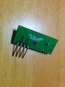
Second problem was where to plug it. The answer was the line of holes where the RF module is in the Sonoff RF. Only two of those pins are tied to the ESP8266, the closest to the relay are GND and 3V3. Could I be so lucky? NO. The receiver I have is the standard RFLink [Aliexpress] and such and has 4 pins: GND, DATA, DATA and VCC. Besides, the module just did not fit so close to the relay so the first pin would go in the second hole (the 3V3 hole)… OK, time for the X-Acto knife, the iron and the dremel.

RF receiver

The RF receiver. I removed the black plastic around the pins to solder it closer to the board, otherwise it won’t fit in the case.

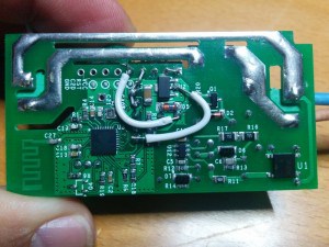
First I cut the traces leading to the 3V3 pin in the RF row of holes (that’s the second hole counting from the relay). There are surface traces on both sides of the board, so I had to cut both and then bridge them together again. Then I soldered the module in the 2nd, 3rd, 4th and 5th holes. I brought GND from the 1st to the 2nd hole, I then connected the DATA pin to the GPIO14 in the perpendicular row of pins through a voltage divider to ground to lower the 5V from the module to 3V3. A 10K and 20K 0805 SMD resistors do the job, but it was really hard to solder them between the pins… Next I soldered the VCC pin of the RF module to a spot in the board I checked was connected to the 5V rail.

Sonoff Hack

Check the cut just by the LDO, there is another one in the same spot in the other side of the board. But cutting those traces removes power from the ESP8266 so I had to wire it again (it’s the white wire in the right). The other white wire powers the RF module with 5V. You can also see the GND bridge between pins 1 and 2 in the top row and the voltage divider from the DATA line to the GPIO14 and GND pins.

Sonoff hack

I also had to dremel a bit the case to allow some room for the module

Done. A bit of a mess but it worked!

"My" Sonoff RF

“My” Sonoff RF

But the maximum distance from the remote to the module was something in the 20cm… until I soldered a 17.3cm wire to the antena hole in the RF module (that 1/4 of a 433MHz wavelength). Now I can be 10 meters away, even with a wall in between and I can still switch it on. And before you say anything: yes, range should be better for a 433MHz module but it’s fine, after all I can still switch it on/off from Australia via the Internet.

ESPurna Firmware

There are some fine control firmwares out there for the ESP8266.  Some of them are generic and let you manage the pins one by one, some of them are more specific for “smart switches” based on the Espressif chip. Most of them have MQTT and Web configuration. Some are small enough so you can flash them Over-the-Air to the 1Mbyte Sonoff. None of them (at least I haven’t found any) have RF capabilities.

So I decided to build my own. After all that’s fun. I’ve named it ESPurna (“espurna” means “spark” in catalan) and it features:

  • WebServer for configuration and simple relay toggle
  • Flashing firmware Over-The-Air (OTA)
  • Up to 3 configurable WIFI networks
  • MQTT support with configurable host and topic
  • Manual switch ON/OFF with button
  • Support for custom RF module (check blog post)
  • Visual status of the connection via the LED
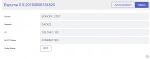
ESPurna status page

ESPurna status page

ESPurna administration page

ESPurna administration page

As always, if you are interested in the firmware it is in a espurna repository in bitbucket.

“Wiring” it.

Final step is to “wire” it all together. The Sonoff with the ESPurna firmware connects to my home WiFi and subscribes to a certain MQTT topic. Upon reception it switches on or off the relay depending on the message payload (0 for OFF, 1 for ON, 2 for TOGGLE). Whenever the relay state is changed it also publishes the new state to the same topic (there is code to avoid recursion). So if you change it manually pressing the button or with the RF remote you still have a record of that.

In my home server I have Node-RED running. A few months ago I switched from a bunch of python scripts to Node-RED for message persistence (in MySQL), notifications and to push data to some online services like Xively or TheThings.io.

With MQTT and Node-RED working adding support for Blynk was a piece of cake. In 10 minutes I had a simple dashboard in my phone from where I could switch the lights on and off. In fact, I’ve spent way more time moving around controls in the dashboard canvas trying to make it look cool (I failed).

Node-RED blynk link

My blynk configuration in Node-RED. So easy!

You know something is well designed when things fit in like magic.

Wow. I feel like I should explain many more things about this project, but there will be a follow up so stay tuned 😉

The post Adding RF to a non-RF ITEAD Sonoff appeared first on Tinkerman.

Manage and persist settings with Embedis

$
0
0

For months I’ve been searching for a settings manager for my Arduino and ESP8266 projects. There are basically two issues to take care of:

  • On memory settings or how do you access to the configuration values from your code
  • Persistence or how do you store the configuration across reboots

For the first issue common solutions in high level languages are key-value solutions in the form of containers or hash arrays. But C++ is not so high level and the ATMega328 or the ESP8266 are nothing more than microcontrollers so resources are limited. Common patterns are simple variables, container classes or structures. They all have the same problem: they are mostly static, if you want to add a new setting you have to change the code and flash it to your controller.

For the second issue some microcontrollers have some type of EEPROM, like the ATMega328 in the Arduinos. The ESP8266 doesn’t have one so it needs an external SPI Flash memory. Using the file system partition in the ESP modules to store a configuration file with all the project settings is feasible. It is persistent across reboots but it gets deleted when you upload a new file system binary. You could use an external memory or make use of “reserved” memory space for you own purposes like Peter Scargill proposes in a recent post.  But if you are using Arduino Core for ESP8266 it already defines a memory layout that reserves a 4Kb block to emulate EEPROM and provides a library to access it that it’s (mostly) API compatible with the Arduino EEPROM library.

Meet Embedis

The Embedis library is the magic trick that solves all the issues above. It provides a key-value type access to your settings, you can set (both updates or creates), get and delete them, list them, query if a certain key exists,… and you can persist them in different storage solutions, in particular in the (emulated) EEPROM.

Embedis commands

Listing commands, querying dictionaries and keys

The library is really easy to use. Just initialize an embedis object and throw this code in your setup and loop methods and you are good to go (if you don’t need console management you can forget the loop part).

Embedis embedis(Serial);

void setup() {

    ...

    EEPROM.begin(SPI_FLASH_SEC_SIZE);
    Embedis::dictionary( F("EEPROM"),
        SPI_FLASH_SEC_SIZE,
        [](size_t pos) -> char { return EEPROM.read(pos); },
        [](size_t pos, char value) { EEPROM.write(pos, value); },
        []() { EEPROM.commit(); }
    );

    ...

}

void loop() {

    ...

    embedis.process();

    ...

}

The previous code works on ESP8266 devices, if you are using an Arduino you don’t need any parameter in the “begin” method but you will need to define a proper size for the dictionary.

Then you just have to get and set your settings and they are automatically persisted to EEPROM:

String ssid;
Embedis::get("ssid", ssid);

... (the user changes the ssid from the web interface, for instance) ...

Embedis::set("ssid", ssid);

The library stores the settings in the EEPROM starting from the end of it backwards. So you can still use the beginning of the memory to store your own values (relay statuses, for instance) provided that you use less than the available EEPROM size between both.

Goodies

The library comes with some nice bonus features, like console management and custom commands. You can modify all your settings from your terminal connection or eventually create your own commands to manage your wifi, reboot the board or execute any administrative options on your device.

Some of the built in commands let you manage your key-value database directly from console or publish o subscribe to topics. This last feature could be used, for instance, to enable specific debug messages. Instead of simply dump debug messages to console we can:

Serial.println("[WEBSERVER] Request /index.html");
Embedis::publish("webserver", "[WEBSERVER] Request /index.html");

The message won’t be displayed unless you subscribe to the “webserver” topic from the console with:

subscribe webserver

You will then receive only the messages for that topic (and not the “wifi” or “sensor” ones, for instance).

subscribe

Credits

The Embedis library is an open source, community supported project, initially developed by David Turnbull, Tom Moxon and PatternAgents, LLC as part as the thingSoC initiative.

thingsoc_model

I’m not associated in any way to Embedis, thingSoC or PatternAgents, nor I had any previous contact with them. My intention with this post is to give credit to a tool that has solved me a problem in a way that I find both elegant and efficient. A perfect match.

The post Manage and persist settings with Embedis appeared first on Tinkerman.

Sonoff SC with MQTT and Domoticz support

$
0
0

Last December Itead Studio updated their Home Automation product line with a new and different product. The main difference is that it doesn’t have a relay and it’s mainly sensors and no actuator (if we don’t define a notifying LED as an actuator). The Sonoff SC is a sensor station that packs a DHT11 temperature and humidity sensor, a GM55 LDR, an electret microphone with an amplifier circuit and a Sharp GP2Y1010AU0F dust sensor in a fancy case that looks like it was originally meant for a speaker.

The device is packs an ESP8266 as expected and is compatible with the eWeLink app. But, such a collection of sensors, with 3 of them having analog interfaces, cannot be run from the single-ADC ESP8266 so Itead has thrown in a good old ATMega328P to drive the sensors and report the Espressif with the data.

The outside

The first thing that draw your attention about the Sonoff SC is it’s casing. It’s kind of a truncated hexagonal-ish pyramid with a round grid on top and a rounded bottom. Seriously, somebody had a good time designing this. It looks a lot like a intricate speaker and actually that’s what it is. The reset/flash button sticks out shamelessly from a hole labelled “Audio” on one side of the enclosure.

20170105_125958s

Side by side with the fake audio hole there is an microUSB connector that’s only for powering the device (no data lines connected) and a microSD slot. The microSD reader is connected to the ATMega328P and I’m not sure what original purpose it has but I can think on a couple of good things to do with it.

On the bottom you have 4 black screws. Remove them to gain access to the insides of the device.

20170105_125942sThe insides

20170105_131332s

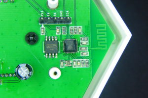
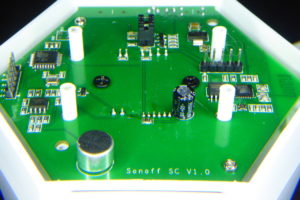
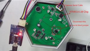
Once the 4 screws are removed it can still be a little tricky to take the PCB out from the enclosure since the button shaft leaves little room to lift the PCB from the plastic holders. Meanwhile you try to remove it, take a look at the components on that bottom side of the PCB. There you can find the controllers and programming headers.

20170105_130308s

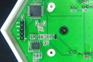
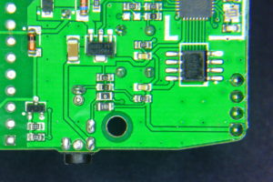
The ATMega328P microcontroller with a 16MHz crystal. The SO-8 IC is a SGM358 dual op-amp used to amplify the electret signal. You can also see a header with 5V, TX, RX, GND and RST.

20170105_130321s

On the opposite site you have the ESP8266 IC with a Winbond 1Mbyte flash memory. You can see the PCB WiFi antena and the programming header with all the needed pins plus the SDA pin. The button is attached to GPIO0 so press it while powering the board to get into flash mode.

20170105_130416s

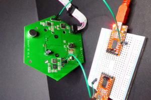
A perspective view fo the bottom side of the PCB. Three more things to note: the jumpers in the center-top of the image connect the RX and TX lines of the ESP8266 and the ATMega328P. Left of that, by the ATMega IC you have an unpopulated ISP header. You will have to solder a 2×3 header here to program the Atmel IC. Also, you have the Electret Mic in the forefront.

20170105_131503s

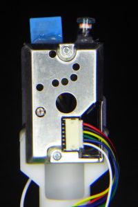
The other three sensors are pleaced on a plastic holder and fit inside the cone of the device. They are hot-glued between them and using standard JST connectors, so replacing them should be no problem…

Upgrading the Sonoff SC

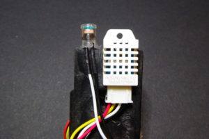
There are a couple of simple, almost out-of-the-box, upgrades you can do to your Sonoff SC. First you can easily replace the DHT11 termperature and humidity sensor with a more precise DHT22 (AM2302) [Aliexpress]. Both sensors are pin compatible. You can read great full comparison of them plus the Sensirion SHT71. The DHT22 is better in accuracy and range to it’s cheaper sibling, but it also has a short life expectancy, so after all it’s a good idea to be able to replace it easily.

20170109_235753s

DHT11 and DHT22 (AM2302) side by side. They are pin compatible.

Off course replacing the sensor is not the full story, you will need to add support for the DHT22 to the firmware. More on this later on.

20170109_235853s

The DHT22 is also bigger than the DHT11. Make sure you place it so it does not protude further than the LDR capsule, otherwise you will have problems fitting everything inside the enclosure back again.

There is also an unused connector in the PCB meant for an LED. It’s driven by GPIO D7 in the ATMega328P through a 2N7002 mosfet in reverse logic (set to LOW to turn on). Remember you have an LED on the PCB as well driven by GPIO13 of the ESP8266 also in reverse logic. The 5V pin is connected directly to the USB supply, so if you have a good power supply you may as well connect here an WS2812 LED strip or ring for some colourful notifications. You will need a GND connection too but there are quite a few available (and properly labelled) on the board already.

20170105_131628s

The LED connector side by side to the dust sensor one.

New firmware for the Sonoff SC

This custom Sonoff SC firmware is released as free open software and can be checked out at my SonoffSC repository on Github.

So after making myself comfortable with the hardware of the device I started putting together some pieces grabbing code from other projects like the ESPurna firmware. The goal was to replace the code in the ATMega328 and the ESP8266 microcontrollers to be able to integrate the Sonoff SC into my home network. That means no cloud, that means MQTT.

While doing that I have added some features that came almost for free since I had already worked on them in other projects: Domoticz support for those that use that home automation platform and a “clap monitor“. Yes. Clap your hands to switch on/off the lights.

Just like the original firmware, this custom firmware monitors temperature, humidity, noise level (in %), dust (in mg/m3) and light (in %).

Communication

First thing was to be able to send messages between the ATMega328P and the ESP8266. Itead Studio provides a simple firmware for the ATMega328P in the Sonoff SC wifi page. The firmware is a good starting point but I don’t like it’s architectured. Everything is too coupled.

So first thing was to create a communications library between both microcontrollers. I started looking for similar solutions and found out the SerialComm library by fjctp. It was almost what I was looking for but I liked the AT commands approach, one char keys are too minimal and naming is important. So I wrote the SerialLink library that allows me to:

  • Compatible with AVR and ESP8266 ICs
  • Define custom commands (the library is agnostic) like AT+TEMP
  • Query command management (AT+TEMP=?)
  • Optional automatic ACK responses
  • Tolerant to noise in the line (debug output from the other controller)
  • Callbacks for get and set values from the application
  • Custom separator (=), terminator (\n) and query (?) chars
  • Currently, it only accepts integer payloads

In the picture below you have a sample of the communication between both microcontrollers. The ESP8266 debug messages are quite verbose but only those starting with AT+… are answered by the ATMegae328P. These are configuration messages “AT+EVERY=60” (set update interval to 60 seconds), “AT+CLAP=1” (enable clapping monitor) and “AT+PUSH=1” (enable message push from the ATMega328P to the ESP8266). Further down the log you start seeing MQTT messages due to push messages from the AVR about a clap code or sensor data.

comms

The SerialLink library is currently bundled into my SonoffSC repository. I will create it’s own repo soon.

MQTT and Domoticz

MQTT and Domoticz integration was easy since most of the code was already there in the ESPurna firmware. I configured the communication link for push messages so in the ESP8266 side I have a callback function that gets all the messages from the ATMega328P and dispatches them to the different outputs.

In this code fragment you can see how message keys are matched and messages are forwarded to three different clients: MQTT, Domoticz and broadcasted to websocket clients like the web interface.

bool commsSet(char * key, int value) {

    char buffer[50];

    if (strcmp_P(key, at_code) == 0) {
        mqttSend(getSetting("mqttTopicClap", MQTT_CLAP_TOPIC).c_str(), value);
        return true;
    }

    if (strcmp_P(key, at_temp) == 0) {
        temperature = (float) value / 10;
        mqttSend(getSetting("mqttTopicTemp", MQTT_TEMPERATURE_TOPIC).c_str(), temperature);
        domoticzSend("dczIdxTemp", temperature);
        sprintf(buffer, "{\"sensorTemp\": %s}", String(temperature).c_str());
        wsSend(buffer);
        return true;
    }

    ...

}

Clap monitor

Now, this is more like a game feature. Don’t know if it’s really useful but it’s certainly fun to play with. Have you ever wanted to move someone by clapping your room lights into romantic mode? Well, this feature is about that.

The algorithm for clapping recognition is somewhat hard if you want to make it reliable, remove false positives and avoid “losing” messages. It’s not certainly suited for a noisy environments (I have kids at home…). My current approach is:
  • The ATMega samples the mic analog output (amplified) in 20ms windows and calculates peak-to-peak values
  • If peak-to-peak value is higher than a certain threshold during N consecutive time windows it flags it as a clap as remembers the current time in milliseconds
  • From the second clap on it stores the time between claps (there is also some debouncing code here)
  • After the last clap times out it checks if it has recorded any intervals (so that it has sensed a minimum of two claps in a row).
  • Clap intervals are coded into binary values. The value always starts with a 1 and each interval pushes a new bit from the right ad shifts everything up. The first interval length is considered a “short” or a 0. If an interval is at least 1.5 times bigger than the first one it is read as a “long” or a 1.
  • Finally the intervals array is reset and everything starts over again

This way I can encode clapping patterns as one byte codes. Two claps are always a “short” so it will be coded as b00000010 or 2. Three claps evenly spaced in time will be a b00000100 or 4. But if you leave a longer time (less than a second) between the second and third claps you get a b00000101 or 5.

I admit it’s somewhat weird but you easily get used to it. “Clap, clap,… clap, clap” (that’s a 10) and switch on the mirror light. “Clap, clap, clap, …. clap” (that’s an 9) and there goes the living room one.

Right now clapping codes are sent by MQTT to a user defined topic. So it’s a matter of having a service somewhere in you local network translating them to MQTT topics to perform different actions. This is a my test flow in Node-RED at home:

nodered-clap

And the code of the “matching” function node is below. Those are ESPurna devices, payload 2 means toggle relay.

if (msg.payload == 9) {
    msg.topic = '/home/living/lamp/relay/0';
    msg.payload = 2;
} else if (msg.payload == 10) {
    msg.topic = '/home/mirror/light/relay/0';
    msg.payload = 2;
} else {
    msg = null;
}
return msg;

And in the future…

There are some features I’d like to add in the future. One thing is that the device has a microSD slot connected to the SPI lines of the ATMega328P. Log sensor data to an SD card could be an option here for non-connected mode.

20170105_131406s

Also I’d like to be able to map clap codes to MQTT topics, hence not needing an external service like NodeRED to do that.

A neat feature would be to be able to OTA flashing the ATMega328P form the ESP8266. It should be possible with a minimum hardware hack: wiring the RST pin in the ATMega328P header to the SDA (GPIO2) pin in the ESP8266 header to reset the AVR programatically.

Also, there are some spare GPIOs available in the board that could be used to add more sensors (the SPI header exposes 3 digital pins, but shared with the SD). Ideas?

Flashing the ESP8266

Flashing the ESP8266 is very easy since the header close to it has all the required connections (3V3, TX, RX, GND) and the button is connected to GPIO0. Press and hold the button while powering the board to set the ESP8266 into flashing mode. You will have to remove the TX jumper in the board to avoid the ATMega328P to interfere in the upload process.

My recommendation is to flash an OTA enabled firmware as soon as possible as use OTA from then on to update the ESP8266 firmware. This way you can keep the jumpers in place and debug the communications to the AVR IC.

Flashing the ATMega328P

The ATMega328P comes flashed with the Arduino bootloader so all you have to do is connect a USB to UART programmer [Aliexpress] to it and flash it from the Arduino IDE or PlatformIO. Notice that labels in the header are from the programmer point of view (weird). So wire RX to your programmer RX, TX to your programmer TX and RST to DTR. Use 5V logic. Also, you don’t want the ESP8266 interfere with the upload so remove the RX jumper that connects both microcontrollers. Actually remove both of them or the ESP8266 might complain with so much noise.

sonoff-sc-pcba

The ATMega328P comes with the Arduino bootloader so you can flash it using a USB to UART programmer (and FTDI-like). You will have to unbridge the connections to the ESP8266 to do it to avoid the ESP8266 interfere in the upload process. Photo by Itead Studio.

But, if you have an AVR programmer like the USBASP v2 [Aliexpress] below, it might be a better option to program the ATMega328P using the unpopulated ISP header in the board. This way you won’t have to disconnect the jumpers between both controllers and have a stable test bed

20170110_005549s

The USBASP programmer I use to flash the firmware in the ATMega328P

Debugging

I’m using the ISP header to flash the ATMega328P and OTA to update the firmware in the ESP8266. This way I have everything connected and I can debug both microcontrollers using two USB to UART boards.

I use only RX lines connecting the RX of programmers to the RX pins in both headers (remember: RX to RX). Grounds are shared through my computer, but you might have to connect those too for better reliability.

20170110_005853s

Test and debug. ISP for uploading ATMega328P firmware, OTA for the ESP8266 and two RX llines to get debug messages from both microcontrollers.

Interface

The application web interface is stored in the ESP8266 using the same compression techniques I use for the ESPurna firmware. Right now you can:

  • Check the current values from the sensors
  • Configure up to 5 different WiFi networks (including the option for static IP)
  • Configure the MQTT connection and topics for the different sensor data
  • Configure the integration with Domoticz
  • Change the hostname (used for the DNS discovery feature: http://myhostname.local)
  • Change the sensor update interval
  • Enable/disable the clap monitor feature

The interface is based on jQuery and PureCSS. Here you have screenshots from the pages in the interface so you can get a better idea of what it can do at this moment.

sonoffsc-0-1-0-status

sonoffsc-0-1-0-general

sonoffsc-0-1-0-wifi

sonoffsc-0-1-0-mqtt

sonoffsc-0-1-0-domoticz

Right now it’s a fully working firmware replacement for the Sonoff SC. You will maybe miss some features from the original firmware. Let me know which ones. Use Github (link below) to report issues or feature requests.

This custom Sonoff SC firmware is released as free open software and can be checked out at my SonoffSC repository on Github.

Any comments are more than welcome.

The post Sonoff SC with MQTT and Domoticz support appeared first on Tinkerman.

Power monitoring with Sonoff TH and ADC121

$
0
0

Lately I’ve been quite busy with the ESPurna firmware. It’s growing bigger and gaining some momentum. It’s really fulfilling to see other people using it and reporting back. But at the same time it’s very time consuming. Last Saturday I released version 1.5.0 with some new functionalities and bug fixes and I decided to use some of my free time over the weekend to work on a project that’s been waiting for a month in the shelf.

A few weeks ago I was playing with the Sonoff TH and I wrote a post about its sensor interface and the possibility of using lots of different digital sensors, including I2C sensors since the board can be easily hacked to export 2 digital pins over that interface.

And having I2C not only increases the number of potentially usable sensors but also opens the possibility of using I2C Analog to Digital converters to overpass the lack of analog inputs in the device. Here it comes the Texas Instruments ADC121 (datasheet), an 12-bit precision ADC with I2C support priced 2.74€ in quantities of 1.

Hacking the Sonoff TH

In my previous post about the Sonoff TH I already mentioned what to do to export a second GPIO in the 2.5mm jack output. It’s really simple, a 0Ohm resistor to bridge a pad (or a blob of solder) and a pull-up resistor if you plan to use it as I2C.

Hardware modifications to a Sonoff TH16

Two 0805 resistors (the noticeably bigger ones). A 0Ohm one to bridge the pad and connect the first ring to GPIO4 and the second one is a 5k1Ohm pull-up.

The think that puzzles me is that the pads for those 2 resistors are already there, but unpopulated. Obviously the engineers at Itead Studio designed a connector with 2 digital GPIOs but during the manufacturing it was decided to leave only one accessible. After all Itead is selling 2 sensors for the TH that both use just one digital pin, so I guess it was a money-driven decision, but still… it’s only two more resistors!

ADC121 board with connector for a 3.5mm CT jack

The idea was to have a small breakout board with an ADC and a more standard 3.5mm jack, the same size most of the non-invasive current clamps out there use. I decided to do a board with a single channel ADC121C027 by Texas Instruments.

Sonoff ADC121 board

The two sides of the Sonoff ADC121 board. It has pads for optional I2C pull-ups and a burden resistor in case your CT doesn’t have one already built-in. Also there is a pad to select the I2C address of the device.

The decision on what ADC to use was between the ADS1115 I already had experience with and the ADC121 family, specifically the ADC121C021 in VSSOP package and the ADC121C027 in SOT package. The ADS1115 has 4 16-bit ADC channels (or 2 differential) and 4 hardware selectable possible addresses. The ADC121 on the other side is a single channel 12-bit ADC with 3 possible I2C addresses. But they are half the price…

Since the goal was to create a current sensor compatible with the Sonoff TH and most of the times you would like to measure the current flowing through the same Sonoff, one channel is enough. Besides the I2C protocol allows to add multiple slaves to the same bus so there is always the possibility to stack different boards to connect different current clamps to the same Sonoff TH. Actually, modern houses here use to have 3 different power phases, so that seems a good number for the maximum number of addresses I could use in a single device.

So I decided to go for the cheaper ADC121 since it has 3 possible addresses and 12-bit ADC is enough for the measurements I want to do. I have a 30A/1V YHDC clamp and 12bit resolution over a 3.3V reference voltage means around 5-6W per unit (230V * 30A/V * 3.3V / 2^12 ~ 5.56W). Granted I will have some noise so it won’t be able to detect LED lamps or small home electronics like mobile charges and such, but it will be OK for traditional bulbs (yes, we still have them), heaters, washing/drying machines, fridges, microwaves,…

20170123_011637s

The board populated. The holes serve as strain relievers and they do their job very well. Also note there are no pull-ups in the board since the Sonoff TH already have them (in both lines now that I have added them)

Sonoff ADC121 board bottom

On the bottom side there is the ADC121, some decoupling capacitors and the voltage bias (R5 and R6). Also the burden resistor is unpopulated since my current clamp has one built-in.

To solder the ADC121 I used solder paste and a hot gun. I’m still newbie using it but I’m improving. Actually, the hardest part was to know the right orientation for the IC. The footprint I had has a dot mark by pin #1, but the SOT6 I received has no dots anywhere, just an X31C label over a line running along the long side.

After investigating a bit I learnt that, usually, if you place the part so you can read the label the pin #1 is in the bottom-left of the IC. Good to know!

Sonoff ADC121 OSHPark render

In the render OSHPark generates you can clearly see the dot mark in pin #1

20170123_011915s

See the label? If you can read it (so it’s not upside down) the bottom-left pin is pin #1

EmonLiteESP with ADC121 support

The EmonLiteESP library is released as free open software and can be checked out at my EmonLiteESP repository on Bitbucket.

Once I had the board I wanted to write some code to test it. There are no ADC121 libraries out there, at least none the I have found. But the functionality I needed was so simple I decided to go straight to the code.

You might know that some time ago a wrote a simple power monitor library for the ESP8266 platform inspired in the EmonLib library for Arduino. The EmonLiteESP library does not implement all the functionality of the original library for Arduino and it’s not API compatible. It only monitors current, no voltage, so you can not get active power, only apparent power. But on the other side the reading is not tied to a specific analog GPIO. Instead you have to define a function callback that will return the analog reading using whatever sources you want, in particular using an I2C ADC.

It might sound complicated, but it’s not. The simplest function would be that returning the value from an analog pin:

unsigned int currentCallback() {
    return analogRead(CURRENT_PIN);
}

You will then pass this function to the library constructor so it knows how to get the reading. Much more flexible. Because now I want to get the value from an ADC121:

unsigned int currentCallback() {

    unsigned int value;

    // Ask for a reading
    Wire.beginTransmission(ADC121_ADDRESS);
    Wire.write(ADC121_REG_RESULT);
    Wire.endTransmission();

    // Get value (12 bits in 2 bytes)
    Wire.requestFrom(ADC121_ADDRESS, 2);
    if (Wire.available() &amp;amp;amp;lt;= 2) {
        value = (Wire.read() &amp;amp;amp;amp; 0x0F) &amp;amp;amp;lt;&amp;amp;amp;lt; 8;
        value |= Wire.read();
    }

    return value;
}

You see, the rest of the code does not change. This pattern is called the strategy pattern in books because it lets you define what strategy the library should use to execute a certain action, like getting an analog value.

Using the Brzo I2C library

The Wire library is part of the Arduino Core for ESP8266 and is API compatible with the Arduino library with the same name. But recently I knew about an implementation of the I2C protocol written in assembly (!!!) specifically for the ESP8266 platform by Pascal Kurtansky. The Brzo I2C library is open source and it’s available in the PlatformIO library manager.

What does it mean it’s written in assembly? Well, basically it means that it’s fast. How fast? A lot faster than the Wire library. In the EmonLiteESP repo you can find two examples for the ADC121, one using the Wire library and a second (adc121_fast) using Pascal’s implementation. Running the example using the Wire library with 1000 samples takes 544ms for each reading. The same with the Brzo I2C library takes only 85ms!! That’s 6.4 times faster!! Amazing. Actually you have to be sure you get at least one full period of the current wave. For a 50Hz system that’s 20ms. So 1000 samples are still 4 full periods.

The problem with the 544ms, aside from the obvious fact that it takes more time, is that 1) you get less samples per period, so your wave representation is very pixelated, so to say, and 2) you can get into problems with your wifi connection or other services that might need more attention.

Let me copy here the full example of the ADC121 using the Brzo I2C library. Some things to notice:

  • Same as with the Wire library for ESP8266 you can choose which two GPIOs to use as SDA and SCL. In the Arduino boards (in ATMega328 controllers) these are fixed in hardware.
  • The Brzo I2C library always uses buffers to send and receive data.
  • You have more fine grain control over the protocol, like SCL frequency and clock stretch time.
  • The current callback I talked about before is implemented here as a lambda function, that’s the “[]() -> unsigned int { …” stuff. There is no need to do it this way.
/*

EmonLiteESP ADC121 Example using Brzo I2C library

Energy Monitor Library for ESP8266 based on EmonLib
Currently only support current sensing

Copyright (C) 2017 by Xose Pérez &amp;amp;amp;lt;xose dot perez at gmail dot com&amp;amp;amp;gt;

This program is free software: you can redistribute it and/or modify
it under the terms of the GNU General Public License as published by
the Free Software Foundation, either version 3 of the License, or
(at your option) any later version.

This program is distributed in the hope that it will be useful,
but WITHOUT ANY WARRANTY; without even the implied warranty of
MERCHANTABILITY or FITNESS FOR A PARTICULAR PURPOSE.  See the
GNU General Public License for more details.

You should have received a copy of the GNU General Public License
along with this program.  If not, see &amp;amp;amp;lt;http://www.gnu.org/licenses/&amp;amp;amp;gt;.

*/

#include &amp;amp;amp;lt;Arduino.h&amp;amp;amp;gt;
#include "EmonLiteESP.h"
#include "brzo_i2c.h"

// -----------------------------------------------------------------------------
// Configuration
// -----------------------------------------------------------------------------

// I2C CONFIGURATION
#define I2C_SDA_PIN             4
#define I2C_SCL_PIN             14
#define I2C_CLOCK_STRETCH_TIME  200
#define I2C_SCL_FREQUENCY       1000

// ADC121 Address
#define ADC121_ADDRESS          0x50

// ADC121 Registers
#define ADC121_REG_RESULT       0x00
#define ADC121_REG_ALERT        0x01
#define ADC121_REG_CONFIG       0x02
#define ADC121_REG_LIMITL       0x03
#define ADC121_REG_LIMITH       0x04
#define ADC121_REG_HYST         0x05
#define ADC121_REG_CONVL        0x06
#define ADC121_REG_CONVH        0x07

// If you are using a nude ESP8266 board it will be 1.0V
// If using a NodeMCU there is a voltage divider in place, so use 3.3V instead.
#define REFERENCE_VOLTAGE       3.3

// Precision of the ADC measure in bits. Arduinos and ESP8266 use 10bits ADCs.
// The ADC121 is a 12bits ADC
#define ADC_BITS                12

// Number of decimal positions for the current output
#define CURRENT_PRECISION       2

// This is basically the volts per amper ratio of your current measurement sensor.
// If your sensor has a voltage output it will be written in the sensor enclosure,
// something like "30V 1A", otherwise it will depend on the burden resistor you are
// using.
#define CURRENT_RATIO           30

// This version of the library only calculate aparent power, so it asumes a fixes
// mains voltage
#define MAINS_VOLTAGE           230

// Number of samples each time you measure
#define SAMPLES_X_MEASUREMENT   1000

// Time between readings, this is not specific of the library but on this sketch
#define MEASUREMENT_INTERVAL    10000

// -----------------------------------------------------------------------------
// Globals
// -----------------------------------------------------------------------------

EmonLiteESP monitor;

// -----------------------------------------------------------------------------
// Energy Monitor
// -----------------------------------------------------------------------------

void powerMonitorSetup() {

    // Init I2C protocol
    brzo_i2c_setup(I2C_SDA_PIN, I2C_SCL_PIN, I2C_CLOCK_STRETCH_TIME);

    // Set the ADC121 fo manual readings (no automatic sampling)
    uint8_t buffer[2];
    buffer[0] = ADC121_REG_CONFIG;
    buffer[1] = 0x00;
    brzo_i2c_start_transaction(ADC121_ADDRESS, I2C_SCL_FREQUENCY);
    brzo_i2c_write(buffer, 2, false);
    brzo_i2c_end_transaction();

    // Setup power monitor
    monitor.initCurrent([]() -&amp;amp;amp;gt; unsigned int {

        unsigned int value;
        uint8_t buffer[2];

        // Ask for a reading
        brzo_i2c_start_transaction(ADC121_ADDRESS, I2C_SCL_FREQUENCY);
        buffer[0] = ADC121_REG_RESULT;
        brzo_i2c_write(buffer, 1, false);

        // Read the value
        brzo_i2c_read(buffer, 2, false);
        brzo_i2c_end_transaction();
        value = (buffer[0] &amp;amp;amp;amp; 0x0F) &amp;amp;amp;lt;&amp;amp;amp;lt; 8; value |= buffer[1]; return value; }, ADC_BITS, REFERENCE_VOLTAGE, CURRENT_RATIO); monitor.setPrecision(CURRENT_PRECISION); } void powerMonitorLoop() { static unsigned long last_check = 0; if ((millis() - last_check) &amp;amp;amp;gt; MEASUREMENT_INTERVAL) {

        unsigned long start = millis();
        double current = monitor.getCurrent(SAMPLES_X_MEASUREMENT);
        Serial.printf("[ENERGY] Sampling time: %ldms\n", millis() - start);
        Serial.printf("[ENERGY] Power now: %dW\n", int(current * MAINS_VOLTAGE));

        last_check = millis();

    }
}

// -----------------------------------------------------------------------------
// Main methods
// -----------------------------------------------------------------------------

void setup() {
    Serial.begin(115200);
    powerMonitorSetup();

}

void loop() {
    powerMonitorLoop();
    delay(1);
}

The post Power monitoring with Sonoff TH and ADC121 appeared first on Tinkerman.

Fenderino, the coolest guitar

$
0
0

Last February 7 I attended a workshop at a the SokoTech in Barcelona to assemble my own Fenderino, the coolest guitar ever (my knowledge about guitars is very limited, so take this sentence with a grain of salt).

The guitar is actually a shield for the Arduino UNO and has been designed by the people at abierto.cc, an initiative aimed to provide open(-sourced) tools for educators, created amongst others, by David Cuartielles, co-founder of Arduino. The shield is inspired by the works of two very good friends of mine: Marc Sibila (@marcsibila) and Jordi Divins (@jdivins). You really should be following these guys, they are doing very special things as Instròniks.

The Fenderino

The shield itself is a beauty.

The shape resembles a Fender Stratocaster and the purple colors would appeal Prince himself. But that’s not everything. A few details make it really shine. The 4 LED brick for the visual notifications is one of those components you invent a project just to be able to use them. The item is a KINGBRIGHT L-875/4IDT and Cuartielles pointed me to the only source I have found for it: farnell.com. It sells for 1.34€ a piece.

The other detail that really stands out is the common cathode 4x 200ohm resistor array. Not as uncommon as the LED array, it limits the current to the LEDs on the array but it doubles as the bridge of the guitar. Nice detail.
20170210_145715s20170210_145529s

The 9 buttons cover a complete octave plus one note (from C to C) and the two potentiometers are used in the sample sketches to change the octave (actually the pitch of the first button) and the volume. There is also a handy 3 positions switch to use different configurations.

20170210_145301s

Finally the output can be the builtin high quality buzzer or your headphones (or you HiFi system) connected to the 3.5mm jack out.

20170210_145511s20170210_145517s

Open Source Software & Hardware

On the workshop we had the opportunity to test different sample sketches, from very simple ones to test the welding connections to scales, polyphonic sounds and a simple but amazing voice synthesizer using the Talkie library by Peter Knight.

Hardware files (KiCAD) and sketches for the Fenderino will be open source. They are not yet available but Cuartielles confirmed me this point just yesterday. As you can see the hardware is licensed CC-SA-BY-NC so basically you can copy and modify it as long as you do proper attribution and you use the same license and don’t make profit out of it.20170423_004500s

Talking MIDI

Playing the guitar was so fun from the very first moment! I was eager to contribute somehow to the project.

At home, we got a new keyboard piano for Christmas and we had it connected to a tablet with the Synthesia app to learn to play some songs. It had been my first contact with the MIDI interface and I had that feeling I could do some fun projects with it. So I started looking at how to turn the Arduino into a MIDI device.

As it turns out, adding MIDI to a USB-capable microcontroller with Arduino is very easy. There are several libraries available. Mainly the MIDIUSB by Gary Grewal & Arduino. But you have to have an USB capable Arduino, like the Leonardo. What if you want to use a Uno?

The Arduino UNO has a second microcontroller on board that handles the USB communications. An Atmel ATMega8u2 or ATMega16u2. That controller talks USB to UART only. But the good thing is that it is a programmable microcontroller (at least in the official Unos, counterfeits sometimes use an FTDI chip or alike which is not reprogrammable).

What we need is to flash that helper microcontroller with a firmware that talks MIDI. Well, there is an open source project that does just that: the HIDUINO. The HIDUINO project “(…) provides a true USB-MIDI device for plug-and-play compatibility on Windows, OSX, and Linux – just like a commercial MIDI controller”. Sounds good.

There are two drawbacks. First you will need an AVR programmer to flash the HIDUINO firmware into the ATMega16u2. There is an ISP header just by the microcontroller to do so.

Second you will need a AVR programmer to flash the ATMega328P from then on since the USB handler IC is no longer doing its job as USB to UART bridge. Actually you only need one AVR programmer so it’s not that much hustle and you can always flash the original firmware for the ATMega16u2 and get back your Arduino UNO.

To flash the ATMega16u2, first checkout the HIDUINO project and grab the arduino_midi.hex file in the compiled_firmwares folder. Connect your programmer like in the pic below. I’m using an USBASP v2.0 [Aliexpress] here with a 10-pin to 6-pin flat cable, an AVRISPMKII [Aliexpress] will also do. To flash it the fast is to call avrdude from the command line (you might need to specify absolute paths for the avrdude binary or config file):

avrdude -v -p atmega16u2 -C avrdude.conf -c usbasp -Pusb -F -U flash:w:arduino_midi.hex -U lfuse:w:0xFF:m -U hfuse:w:0xD9:m -U efuse:w:0xF4:m -U lock:w:0x0F:m

img_20170422_235850s

Flashing the sketch is very similar, you can do it from the IDE but again it will be faster to do it from the console:

avrdude -v -p atmega328p -C avrdude.conf -c usbasp -Pusb  -U flash:w:firmware.hex:i

Check the image to connect the 6-pin flat cable in the right orientation.

img_20170422_235916s

Firmware

The Fenderino MIDI sketch will probably be available as an example from the abierto.cc repository. But if you are curious you can check my repo with only the MIDI example I had worked on.

The Fenderino MIDI sketch is released under the GPLv3 license and can be checked out at my Fenderino MIDI repository on Github.

And play!

Left to right: David Cuartielles, me and Marc Sibila at SokoTech. Uma is the canine in residence.

Left to right: David Cuartielles, me and Marc Sibila at SokoTech. Uma is the canine in residence.

You can now buy the Fenderino shield from the abierto.cc store.

The post Fenderino, the coolest guitar appeared first on Tinkerman.

Secure remote access to your IoT devices

$
0
0

When you are hacking with IoT devices at home you get to face the challenge of accessing remotely to them, that is from outside your home network. I’m not saying your home network is a safe place, beware. But that thing outside, you know, “the Internet”, it’s so scary… Unfortunately, most IoT devices are just not ready for the jungle. Neither the commercial ones, nor the hacked ones you might have. I wouldn’t dare to open a port in my router to anything inside unless it’s encrypted. So what should we do?

Options

There exist different apps that let you control your devices from anywhere you might be. Think of Blynk for instance. You can use SSL with the blynk-library for ESP8266 or Arduino. You can also do MQTT over SSL. But either one eats so much memory you can do very little else. ESP8266 is barely capable of handling one SSL connection, don’t ask it to also perform as a webserver.

The other popular solution is to create a secured entry point to your network and the most common configuration for that is a reverse proxy using Nginx with SSL. This is what I have at home and since I’m doing some changes to it (soon on another post) I have decided to write down here all the steps required to configure a Raspberry Pi as a reverse proxy to access you0 IoT devices (or any other service you might have at home) from the outside in a secure way.

I’m using a Raspberry Pi 3 at home which hosts several services (Node-RED, InfluxDB, Grafana, Mosquitto,…). It uses Raspbian 8 based on Debian Jessie. I guess you could use older version of the RPi but this one is really fast and I have had no problems so far.

Nginx is a web server, just like Apache. I have been using it as a web server for the last 6 years maybe because it’s so much light weight and faster than Apache and you can pretty much anything you want with it. But we will not be setting up a webserver here, but a reverse proxy. Nginx stands out as a reverse proxy precisely because it’s so light weight it adds very little overhead to the communication.

What is a reverse proxy, you might say? A reverse proxy is a service that sits typically on the edge of your network, just behind your router, and retrieves resources from inside the network. While doing that it might do some other tasks like translating adresses, encrypting/decrypting the communication or hidding resources, to name a few. Here we are interested in the encrypting/decrypting part. Our reverse proxy will encrypt the communication going outside our network and decrypt it when it comes back to us. So even thou our devices do not “speak” SSL all the communications going outside our network throught the proxy will be encrypted on behalf of them.


Install Nginx

Ok, hands on. I’m assuming you have a machine with a Debian Jessie OS (be it a Raspbian 8 or any other). If you have some other OS there might be some differences on the commands below but the overall picture should be the same.

First thing to do is to install Nginx. It couldn’t be easier:

sudo apt-get update
sudo apt-get install nginx

Done. You now should have a Nginx server running on your machine. By default it exposes the contents of “/var/www/html/” on port 80 (HTTP, not secured). If you write the URL of the machine on your browser you should see a welcome message from Nginx. Nice.

Install Let’s Encrypt agent

Now let’s install the SSL certificates. We don’t want to use port 80 but 443 (HTTPS) but before disabling it, let’s see how to create and install the certificates. You can create them yourself or use the awesome service Let’s Encrypt. You can easily create and deploy Let’s Encrypt certificates using EFF Certbot. Certbot comes as a command line tool that automates everything.

if you want to install Certbot on a Debian Jessie you will need to install it from the backports repository. Backports are packages that are being “ported back” from newer versions of the OS. The latests stable Debian is 9.1.

echo "deb http://ftp.debian.org/debian jessie-backports main contrib" | sudo tee /etc/apt/sources.list.d/backports.list
sudo apt-key adv --keyserver keyserver.ubuntu.com --recv-keys 8B48AD6246925553
sudo apt-key adv --keyserver keyserver.ubuntu.com --recv-keys 7638D0442B90D010
sudo apt-get update
sudo apt-get install certbot -t jessie-backports

Get SSL certificates for your proxy

Now we just have to tell Certbot to request and deploy a new certificate from Let’s Encrypt. First Certbot will create a key pair and start the communication with Let’s Encrypt providing the public key. Let’s Encrypt must validate that we are administrators of the domain we are requesting the certificate for. So they will provide a challenge: a certain file has to be created under that domain. Certbot will create that file for us, sign the nonce with the private key and tell Let’s Encrypt that we are ready for the challenge. If everything goes OK now Let’s Encrypt will register that our public key is authorized to manage the certificates for our domain. You can read a (probably better) explanation about the process in the how it works page in letsencrypt.org.

So basically Certbot takes care of the whole process. Only, we need to ensure that Let’s Encrypt will be able to read the challenge file from our server under that certain domain. Now, I have dynamic IP at home so I use DynDNS.org services to access my server at home (usually only for SSH communications). Dynamic DNS or even subdomains are not supported by most certificate authorities, but Let’s Encrypt does support them. It may happen that browsers complain about the certificate or you might face an error saying there have been too many requests for a certain domain (like homeip.org, managed by dyndns.org) when requesting the certificate.

To solve this second issue I map a subdomain in one of my public (true) domains to the dynamic domain as a CNAME. So imagine you have a “geek.homeip.net” dynamic domain always pointing at your home IP. And you are also the proud owner of “fibonacci.com” (valued at 55k€ right now). All you have to do is to create a CNAME record in your main domain pointing your dynamic domain:

geek.fibonacci.com.        CNAME  geek.homeip.net.

Of course if you map a domain to your dynamic one you might as well solve the first problem above. For the moment I’m living with it…

You will then issue a request to get the certificates for geek.fibonacci.com. On your home router you will also have to open a port to your proxy server. Opening a port simply means mapping the communications coming to a certain port to a machine inside your network. You will need to look for “NAT” on your router configuration and tell the router to redirect all communications on port 80 (HTTP) to your proxy server. You will need to do the same for port 443 (HTTPS).

Now you are ready to instruct Certbot to request the certificate:

sudo certbot certonly --webroot -w /var/www/html -d geek.fibonacci.com

If you are getting errors double check that you can reach your Raspberry Pi from outside your network. I normally place a file with some random content on “/var/www/html/hello.txt” and then I visit “http://geek.fibonacci.com/hello.txt” from outside my home network, disabling WiFi on my mobile phone, for instance. If there were no problems you can check where the certificate and key have been stored on the system like this:

xose@acrux:~ $ sudo certbot certificates
Saving debug log to /var/log/letsencrypt/letsencrypt.log

-------------------------------------------------------------------------------
Found the following certs:
Certificate Name: geek.fibonacci.com
Domains: geek.fibonacci.com
Expiry Date: 2017-12-01 09:38:00+00:00 (VALID: 89 days)
Certificate Path: /etc/letsencrypt/live/geek.fibonacci.com/fullchain.pem
Private Key Path: /etc/letsencrypt/live/geek.fibonacci.com/privkey.pem
-------------------------------------------------------------------------------

Configure the reverse proxy

Now that we have the certificate let’s configure Nginx to work as an SSL reverse proxy. I usually create a “/etc/nginx/sites-available/proxy” file with these contents:

server {

    # general server parameters
    listen                      443;
    server_name                 geek.fibonacci.com;
    access_log                  /var/log/nginx/geek.fibonacci.com.access.log;       

    # SSL configuration
    ssl                         on;
    ssl_certificate             /etc/letsencrypt/live/geek.fibonacci.com/fullchain.pem;
    ssl_certificate_key         /etc/letsencrypt/live/geek.fibonacci.com/privkey.pem;
    ssl_session_cache           builtin:1000  shared:SSL:10m;
    ssl_protocols               TLSv1 TLSv1.1 TLSv1.2;
    ssl_ciphers                 HIGH:!aNULL:!eNULL:!EXPORT:!CAMELLIA:!DES:!MD5:!PSK:!RC4;
    ssl_prefer_server_ciphers   on;
    
    location /livinglamp/ {

      # header pass through configuration
      proxy_set_header        Host $host;
      proxy_set_header        X-Real-IP $remote_addr;
      proxy_set_header        X-Forwarded-For $proxy_add_x_forwarded_for;
      proxy_set_header        X-Forwarded-Proto $scheme;

      # extra debug headers
      add_header              X-Forwarded-For $proxy_add_x_forwarded_for;

      # actual proxying configuration
      proxy_ssl_session_reuse on;
      proxy_pass              http://livinglamp.local/;
      proxy_redirect          default;
      #proxy_redirect          ^/(.*)$ /livinglamp/$1;
      proxy_read_timeout      90;

    }


}

There as some things here to note. First we specify the server name (geek.fibonacci.com) and we listen on port 443 (HTTPS). Remember you will have to open that port in your router pointing to your reverse proxy machine. Then we configure the certificates, the routes are the same we got previously when running “sudo certbot certificates”. Then we can define as many locations as devices or services we want to map under that domain. Here I just have one (/livinglamp/) mapped to an Itead S20 I have on my living room flashed with ESPurna. The local address of the device is used here (livinglamp.local). As you can guess, we are saying that all traffic comming to “https://geek.fibonacci.com/livinglamp/” should be redirected to “http://livinglamp.local/”. We are translating a public URL to a private one and changing from HTTPS to HTTP.

The tricky part here is the proxy_redirect option. It defines the “translation back” and will depend on how your device fetches other local resources like images, for instance. Also this configuration does not deal with query strings, the part of the URL that comes after the ‘?’.

Autorenew certificates

Once you have this working you can go back to your home router settings and delete or disable the map you did on port 80 (HTTP). The only ports you should open are those meant for encrypted communications (HTTPS, SSL, MQTT of SSL,…).

No. Don’t do that. You will need that port to autorenew your SSL certificates. Let’s Encrypt certificates have a validity of 90 days so you will be reneweing them often or forget and the whole set up  will fail. That’s why autorenewing is cool.

Leave that connection open but beware that anything under “/var/www/html” will be publicly visible. We will be using a crontab to try to renew them weekly, if they are not close to the expirity date it will just end silently. We will have to do it from the root crontab:

sudo crontab -e

The file will probably be populated with some explanation and maybe some crontab rules already. We will add these two lines at the bottom:

@weekly /usr/bin/certbot renew --quiet --no-self-upgrade -w /var/www/html/
@daily  service nginx reload

Basically we are asking the crontab to execute the autorenew procedure once a week, and since Nginx won’t reload the new certificates we are also reloading it once a day.

That’s all. I hope this helps you having a more secure experience accessing your IoT devices from the Internet. Of course any comments or ammends you might have, just use the comments section below.

The post Secure remote access to your IoT devices appeared first on Tinkerman.

Arduino MKR WAN 1300

$
0
0

I’ve been testing quite a few LoRaWan nodes lately for TheThingsNetwork.cat, some based on HopeRF RFM95W (over AVR, ESP8266, ESP32,…) others using Microchip’s RN2483 (an old friend of mine). I have a RAK811 waiting in the INBOX but the last one I’ve been playing with has been the new Arduino MKRWAN 1300 (so new there is no product page yet) and I liked it, quite a lot.

The device is one of the MKR series Arduino is pushing forward. So far the family includes the MKR ZERO (did they name it after the RPi Zero? actually, it’s named after the Cortex-M0+ MCU, and it had that name “far before the RPi”, as David Cuartielles has pointed out), the MKR 1000 with WiFi, the MKR FOX 1200 with SigFox support, the MKR WAN 1300 and the MKR GSM 1400.

They all sport a SAMD21 Cortex-M0+ [pdf, datasheet] 32bit low power ARM MCU clocked at 48MHz, 256Kb of flash memory (to store your code) and 32Kb of SRAM. That’s quite an improvement from the Uno family (ATMega329 / ATMega32u4). It also has a bunch of digital IO, most of them PWM, several ADC of up to 12bits depth, hardware UART, SPI and I2C and even one DAC (!!).

20180130_013123s

But the reason this is my first MKR dev board is its LoRaWan compatible module. A Murata CMWX1ZZABZ that includes a STM32 microcontroller with an AT firmware you can interface with from within your sketches.

20180130_013102s

There is still little information about the board in the Internet. Sure you can find press notes but there is little hands-on stuff yet: the MKRWAN library repo and a “Getting started” repo by Gonzalo Casas from TTN Zurich. Gonzalo uses the Arduino IDE to explain the first steps with the board. But I’m going to write here about my experience using it from my favourite environment: PlatformIO.

Configuring PlatformIO for the MKR WAN 1300

Yes. The MKR WAN 1300 works just fine (almost, see below) with latest Arduino IDE versions. But I just happen to use not Arduino IDE. So I quickly headed to my favourite builder, PlatformIO, listed the supported boards and… no luck. The 1300 was not there.

There are quite a few SAMD21 boards supported, starting with Adafruit’s M0 boards, some Arduino MKR and others. But not the MKR WAN 1300. Next I tried using MKR ZERO board assuming that since it is the minimum common denominator for all MKR boards I could get something out of it. Wrong.

As it turns out there are some small details as the device signature that prevent it from working with other boards. Albeit more obvious differences like available GPIOs in the headers.

20180130_013208s

Long story short, I migrated the configuration from Arduino IDE to PlatformIO, comparing them with other MKR boards already defined. There are two packages that require an update and I have submitted pull-requests for that to PlatformIO. I don’t know what’s the policy they have about supporting Arduino boards. Somewhere I read something that made me think they have an automatic process, but as of today the packages are obviously outdated.

Anyway, the changes are in the AtmelSAM platform (see PR here) and ArduinoSAM framework (PR here). While the PRs are not merged you can install support for any SAMD board and then patch those packages in you .platformio folder.

$ pio boards | grep -i mkr
mkr1000USB            SAMD21G18A     48Mhz     256kB   32kB   Arduino MKR1000
mkrfox1200            SAMD21G18A     48Mhz     256kB   32kB   Arduino MKRFox1200
mkrwan1300            SAMD21G18A     48Mhz     256kB   32kB   Arduino MKRWAN1300
mkrzero               SAMD21G18A     48Mhz     256kB   32kB   Arduino MKRZero

Voilà

The MKRWAN library

No that I can flash the MKR WAN 1300 using PlatformIO let’s go to the LoRaWan part. The people from Arduino have released a library just for that. The Murata module in the device has a STM32 frontend that exposes an AT command interface you can use from the SAMD21 using the MKRWAN library.

Both the firmware for the STM32 (mkrwan1300-fw) and the MKRWAN library are available on GitHub. But you can also install the library using the PlatformIO library manager.

$ pio lib search mkrwan
Found 1 libraries:

MKRWAN
======
#ID: 2009
Support library for MKR WAN 1300

Keywords: communication
Compatible frameworks: Arduino
Compatible platforms: Atmel SAM
Authors: Arduino

Install and test. There is a full example called FirstConfiguration.ino that does it all. Shows the device EUI so you can register it in your TTN backend and allows you to join via OTAA or ABP and send a test message. Cool.

$ cd
$ mkdir -p workspace/mkrwan1300_test
$ cd workspace/mkrwan1300_test
$ pio init -b mkrwan1300
$ pio lib install mkrwan
$ cp .piolibdeps/MKRWAN_ID2009/examples/FirstConfiguration/FirstConfiguration.ino src/
$ pio run -t upload
$ pio device monitor -b 115200
Welcome to MKRWAN1300 first configuration sketch
Register to your favourite LoRa network and we are ready to go!
Your module version is: ARD-078 1.1.2
Your device EUI is: 0123456789abcdef
Are you connecting via OTAA (1) or ABP (2)?
1
Enter your APP EUI
0123456789012345
Enter your APP KEY
01234567890123456789012345678901
Message sent correctly!

Wow. That was amazing for a first test. I was very pleased to see that OTAA worked out of the box. But ABP did not.

After digging a bit on the problem with ABP I hit a dead end when I couldn’t find the documentation for the STM32 firmware. So I decided to open an issue on the library repository on GitHub last Friday and on Monday it was solved. Not bad! As a side note, the STM32 firmware repository was not public yet (that’s why I couldn’t find any docs) but that has changed this Monday 29th January.

Updating the firmware in the STM32 inside the Murata module

Once a solution was proposed I had to flash the firmware on the STM32 and update the MKRWAN library. Fortunately the developer of the library (Martino Facchin, thank you very much) had added a firmware upgrade sketch in the examples folder that includes the latest firmware image in the fw.h file. So I removed the old library, cloned the new one and run the upgrader example:

$ pio lib uninstall mkrwan
$ git clone https://github.com/arduino-libraries/MKRWAN lib/MKRWAN
$ rm -rf src
$ cp -r lib/MKRWAN/examples/MKRWANFWUpdate_standalone src
$ pio run -t upload
$ pio device monitor -b 115200

You will now see the progress of the upgrade and a final “Flashing ok 🙂 ARD-078 1.1.3” message. Good.

And finally: testing it!

Now back to the FirstConfiguration example, flash, open a connection to the device and…

$ rm -rf src
$ cp -r lib/MKRWAN/examples/FirstConfiguration src
$ pio run -t upload
$ pio device monitor -b 115200
Welcome to MKRWAN1300 first configuration sketch
Register to your favourite LoRa network and we are ready to go!
Your module version is: ARD-078 1.1.3
Your device EUI is: 0123456789abcdef
Are you connecting via OTAA (1) or ABP (2)?
2
Enter your Device Address
22334455
Enter your NWS KEY
01234567890123456789012345678901
Enter your APP SKEY
01234567890123456789012345678901
Error sending message

Now what? Well, looking at the TTN console I noticed the message actually went through… Looks like it timed out before receiving the ACK.

20180130_012842s

There are some things to improve yet but the overall initial experience is very good. They are actively working on fixing problems and that even better. Now it’s time to do some real life tests to see if this is a dev board of choice.

The post Arduino MKR WAN 1300 appeared first on Tinkerman.


EEPROM Rotation for ESP8266 and ESP32

$
0
0

The Arduino Core for ESP8266 and ESP32 uses one SPI flash memory sector to emulate an EEPROM. When you initialize the EEPROM object (calling begin) it reads the contents of the sector into a memory buffer. Reading a writing is done over that in-memory buffer. Whenever you call commit it write the contents back to the flash sector.

Due to the nature of this flash memory (NOR) a full sector erase must be done prior to write any new data. If a power failure (intended or not) happens during this process the sector data is lost.

Also, writing data to a NOR memory can be done byte by byte but only to change a 1 to a 0. The only way to turn 0s to 1s is to perform a sector erase which turns all memory positions in that sector to 1. But sector erasing must be done in full sectors, thus wearing out the flash memory faster.

How can we overcome these problems?

EEPROM rotation

These days I’ve been working on a standalone library that wraps the stock EEPROM library and does “sector rotation“. Using more than one sector (a sector pool) to store data and keeping track of the one with the latest valid information.

The library overwrites two methods of the original one: begin and commit. The begin method will load the data from all the sectors in the sector pool one after the other trying to figure out which one has the latest valid information. To do this it checks two values:

  • A 2-bytes CRC
  • A 1-byte auto-increment number

These values are stored in a certain position in the sector (at the very beginning by default but the user can choose another position with the offset method).

The CRC is calculated based on the contents of the sector (except for those special 3 bytes). If the calculated CRC matches that stored in the sector then the library checks the auto-increment and selects the sector with the most recent number (taking overflows into account, of course).

Those special values are stored by the overwritten commit method prior to the actual commit.

With every commit, the library will hop to the next sector. This way, in case of a power failure in the middle of a commit, the CRC for that sector will fail and the library will use the data in the latest known-good sector.

EEPROM_Rotate API

The EEPROM_Rotate library for ESP8266 Arduino Core is released under the Lesser General Public License 3.0 (LGPL-3.0) as free open software and can be checked out at my EEPROM_Rotate repository on GitHub.

The library inherits form the Arduino Core for ESP8266 EEPROM library, and it shares the same API. You can just replace one with the other. The same public methods with the same signature. By default it will use the same sector as with the EEPROM library (sector 1019 for 4Mb boards, sector 251 for 1Mb boards), or you can specify another sector in the constructor. It can behave like a drop-in replacement.

If you define a sector pool size different that one (using the size method). The other sectors are the ones counting from the base one downwards. This means that if we set up a sector pool size of 4 for a 4Mb board using default base sector, the used sectors will be 1019, 1018, 1017 and 1016.

An example would be:

EEPROM_Rotate EEPROM;           // Instantiate the object
EEPROM.size(2);                 // Use two sectors for rotation
EEPROM.begin(4096);             // Use the full sector size to store data
uint8_t data = EEPROM.read(10); // Read a byte at address 10 in the memory buffer
EEPROM.write(data + 1);         // Increase the value
EEPROM.commit();                // Persist data to flash (in a different sector)

Disabling the original global EEPROM object

The original EEPROM library automatically instantiates an EEPROM object that’s already available to use. This consumes little memory (since the data buffer is only created and populated when calling begin). But anyway if you don’t want to have a unused object around you can disable the object instantiation by using the NO_GLOBAL_EEPROM build flag.

OTA (and non-OTA) upgrades

You can use custom memory layouts (see next section) to “reserve” memory sectors for EEPROM rotating like in the section before. But there is no need for it as long as you take some precautions. Basically, if are using more than one sector and you have not reserved them, all of them but the last will be overwritten when doing an OTA upgrade, because OTA images are first stored at the end of the firmware block.

basic-nospiffs-fota
Imagine these scenarios for a 3 sector pool size, with and without SPIFFS block:

rotate-nospiffs-fota
rotate-spiffs-fsota

On both cases all but the last sector get overwritten by the OTA image. What can you do?

Well, the library has a special method called backup that will backup the contents of the current memory buffer to any given sector. If you call it with no parameters it will save them to the last sector in the pool, the one that’s safe from OTA.

So, whenever you do an OTA upgrade (being it firmware or the SPIFFS image) call the backup() method first. The ArduinoOTA library has a onStart callback you can use to backup the contents. Same for the Update class.

There is still one special case that could be a problem: non-OTA upgrades. In a wired upgrade the firmware has no control of the situation and it cannot backup the EEPROM before the upgrade. If your image is large enough it may overwrite the sectors in use for the EEPROM pool. For a firmware image this is very unlikely, only with old 512Kb memory chips you may run into problems when flashing big images.

But when flashing the file system you will always hit this problem, because it always overwrites the full SPIFFS partition. So if you are flashing the SPIFFS partition and want to keep the EEPROM configuration you have two options: a custom memory layout that really reserves more sectors for EEPROM (see below) or upgrade it always over the air and program your firmware so it first backs up the EEPROM contents to the latest sector using backup.

Custom memory layout and auto-discover pool size

Using a custom memory layout could be a good solution to be sure that the information in your sector pool never gets overwritten. Moreover, the library will automatically discover the number of available sectors for EEPROM. These will be the number of sectors after the SPIFFS memory space (or after the application partition if no SPIFFS partition) except for the last 4 (reserved by Espressif).

rotate-custom-fota
This is the original memory layout configuration for a 1Mb flash size board with no SPIFFS space (eagle.flash.1m0.ld):

/* Flash Split for 1M chips */
/* sketch 999KB */
/* eeprom 20KB */

MEMORY
{
  dport0_0_seg :                        org = 0x3FF00000, len = 0x10
  dram0_0_seg :                         org = 0x3FFE8000, len = 0x14000
  iram1_0_seg :                         org = 0x40100000, len = 0x8000
  irom0_0_seg :                         org = 0x40201010, len = 0xf9ff0
}

PROVIDE ( _SPIFFS_start = 0x402FB000 );
PROVIDE ( _SPIFFS_end = 0x402FB000 );
PROVIDE ( _SPIFFS_page = 0x0 );
PROVIDE ( _SPIFFS_block = 0x0 );

INCLUDE "../ld/eagle.app.v6.common.ld"

Program memory is mapped at 0x40200000, so a 1Mb flash memory ends at 0x40300000. Here you can see the end of the SPIFFS block is at 0x402FB000. So there are 20480 bytes after that point. Every sector has 4096 bytes so thats 5 sectors. Given that the last four are reserved there is one left for EEPROM.

Now let’s see this custom layout:

/* Flash Split for 4M chips */
/* sketch 1019KB */
/* spiffs 3040KB */
/* eeprom 16KB */
/* reserved 16KB */

MEMORY
{
  dport0_0_seg :                        org = 0x3FF00000, len = 0x10
  dram0_0_seg :                         org = 0x3FFE8000, len = 0x14000
  iram1_0_seg :                         org = 0x40100000, len = 0x8000
  irom0_0_seg :                         org = 0x40201010, len = 0xfeff0
}

PROVIDE ( _SPIFFS_start = 0x40300000 );
PROVIDE ( _SPIFFS_end = 0x405F8000 );
PROVIDE ( _SPIFFS_page = 0x100 );
PROVIDE ( _SPIFFS_block = 0x2000 );

INCLUDE "eagle.app.v6.common.ld"

Now this is a 4Mb board (like the in the ESP12 modules). Flash memory ends at (0x40200000 + 4 * 1024 * 1024) 0x40600000. Therefore, after the SPIFFS block there are still 32768 bytes or 8 sectors. 4 of them are reserved, so 4 more are available to rotate the EEPROM contents.

ESP32 Partition table

The library for the ESP32 works very much the same way but there are some differences due to the way the stock EEPROM for ESP32 library works. This library (in practice) requires a custom partition table to work. You could use any partition in the default partition scheme but you will want to create a custom one defining as many partitions for EEPROM as you’d like to.

This is not difficult at all, using PlatformIO. If anyone knows how to do it with the Arduino IDE (not touching the core files) then, please, let me know.

PlatformIO

PlatformIO lets you define a CSV file for each environment in your platformio.ini file. Like this:

[env:nano32]
platform = espressif32
board = nano32
framework = arduino
board_build.partitions = partition-table.csv
build_flags = -DNO_GLOBAL_EEPROM

This CSV file defines the different partitions in the SPI flash memory:

# Name,   Type, SubType, Offset,  Size, Flags
nvs,      data, nvs,     0x9000,  0x5000,
otadata,  data, ota,     0xe000,  0x2000,
app0,     app,  ota_0,   0x10000, 0x140000,
app1,     app,  ota_1,   0x150000,0x140000,
eeprom0,  data, 0x99,    0x290000,0x1000,
eeprom1,  data, 0x99,    0x291000,0x1000,
spiffs,   data, spiffs,  0x292000,0x16E000,

Here you can see that we have added two partitions for EEPROM (eeprom0 and eeprom1).

EEPROM32_Rotate API

The EEPROM32_Rotate library for ESP32 Arduino Core is released under the Lesser General Public License 3.0 (LGPL-3.0) as free open software and can be checked out at my EEPROM32_Rotate repository on GitHub.

The library inherits form the Arduino Core for ESP32 EEPROM library, but it uses a slightly different API. Differences are in the constructor. The original EEPROM library for ESP32 has different constructor signatures but only valid at the moment is:

EEPROMClass EEPROM("eeprom0");

To make this library API more consistent, I have decided to change the way you create and ‘populate’ an object:

EEPROM32_Rotate EEPROM;
EEPROM.add_by_name("eeprom0");

Now you may find obvious how to add more partitions to the pool:

EEPROM32_Rotate EEPROM;
EEPROM.add_by_name("eeprom0");
EEPROM.add_by_name("eeprom1");
EEPROM.add_by_name("eeprom2");
EEPROM.add_by_name("eeprom3");

Actually, if all partitions have the same data subtype (usually 0x99, thou this is only a convention) then it’s a lot easier to add them all:

EEPROM32_Rotate EEPROM;
EEPROM.add_by_subtype(0x99);

Now you can use it like a regular EEPROM object:

EEPROM32_Rotate EEPROM;
EEPROM.add_by_subtype(0x99);
uint8_t b = EEPROM.read(0);
EEPROM.write(0, b+1);
EEPROM.commit();

Remember than the stock EEPROM library for ESP32 has a bunch of convenient methods like readLong, readBytes, writeString,… you can also use those!

The post EEPROM Rotation for ESP8266 and ESP32 appeared first on Tinkerman.

M5Stack node for The Things Network

$
0
0

I have a couple of IKEA-like boxes in my home office labeled “Inbox”. They are full of stuff I buy and store waiting for some free time to spend on them. From time to time I pick one of the boxes and take a look at its contents. They are actually full of “wow” stuff. I would buy again most of the things there but at the same time I fear I’m just collecting stuff that will become junk.

I couple of week ago I rescued from one of those boxes an M5Stack Core Development Kit and some other stuff that was there for maybe 6 months.

The M5Stack prototyping platform

M5Stack is a prototyping platform that has taken one (big) step forward the shield idea from the Arduino ecosystem. Starting with the M5Stack Core that packs the all-mighty ESP32 with an SD card slot, speaker, grove connector, power button and LiPo battery charger. But it also has a 320×240 full color LCD screen and 3 action buttons. Some models also include an MPU9250 9dof sensor. Everything in a 50x50x12mm frame.

On top of it (actually on the bottom) you can stack a number of modules. They are all 50x50mm and different heights. These modules add new hardware (GPS, GSM, PLC,…) or options (prototyping zone, LiPo battery). The default bottom module is a thin layer with several male and female headers to have access to most of the available GPIOs of the ESP32, a small LiPo (100mAh?) and 4 neodimium magnets to stick it to a metallic surface.

With a Core and a function module plus the bottom layer you can build a PoC really fast. But the best part is that your PoC will look almost like a finished product. No need to hide it in a fancy box, this thing just looks awesome!

20180609_180619s

You can spot ten, maybe fifteen different modules for the M5Stack on the Internet. But not all of them are available on their store (which is housed in Aliexpress). Maybe some of them are still in beta. Here you have some links and reference prices. These are affiliate links. If you plan to buy any of these products, clicking on these links will help me keep on working on this blog.

Product Link Price
Core Aliexpress ~31€
Core (with MPU9250) Aliexpress ~36€
Battery module (850mAh) Aliexpress ~15€
GPS module Aliexpress ~35€
Proto module Aliexpress ~9€
PLC module Aliexpress ~20€
Faces keyboard (expensive but really cool) Aliexpress ~141€

And, they also have a LoRa module. But wait! I’m not promoting this one because they only sell the 433MHz version… What about the 868MHz, or the 915MHz? Well, this is when this post comes to hand 🙂

The PCB

The PCB is very simple. It just routes the required traces from the radio footprint to the header. I added an additional radio footprint using very little additional space. The RFM69C is a FSK 868MHz radio I use at home in some sensors. You cannot have both radios mounted at the same time, of course, but that’s a corner use case.

The M5Stack RFM95 PCB is released under the CC-BY-SA-4.0 license as free open hardware and can be checked out at my M5Stack RFM95 repository on GitHub.

I chose to use the same GPIOs as the M5Stack 433MHz LoRa module plus a couple for for DIO1 and DIO2:

Function GPIO
MOSI GPIO23
MISO GPIO19
SCK GPIO18
SEL GPIO5
RESET GPIO36
DIO0 GPIO26
DIO1 GPIO16
DIO2 GPIO17

There is also the footprint for a 90 degrees SMA connector in the edge of the board.

m5stack-rfm95-v1-0-20180330-schematic

m5stack-rfm95-v1-0-20180330-layout

20180609_105906s

A matter of headers

The M5Stack modules use 2×15, 100mil pitch, SMD headers, and even thou I had a few of each (male & female) I realized they would not work, at least not the female ones. The antenna connector adds 9mm of height so I needed higher female headers too.

In the end, I decided not to use the SMD header at all and, instead, use normal ones. But not any normal header will do. The usual 2-row female header have not long enough pins (just enough to let you solder them) and the stackable ones have far too long pins (more than 10mm). I happened to have at home a 2×20 row of the right size: a normal female header on one side and just 5mm of pin length on the male side. These are not usual and I’m struggling to find more. As soon as I do I will post here the link.

The header just fits fine, it has the right height on both sides. The only problem I found is that if you stack another module on top of them (on the female side), the contact is loose so I had to use a pair of nylon screws to keep both layers pressed together.

Improvements

So much free space makes me a little nervous. At the same time it’s not a matter of packing stuff there just because you have room. What I will certainly add is a battery connector because it will remove the need to add the battery module. This will allow me to create simple echo nodes with just the Core and the RFM95 layer with a bottom enclosure.

20180609_085421

Another issue to take into consideration is the header problem above. If I do not find proper through hole headers I will have to look for other options. Like using high SMD headers…

The enclosure

I designed two different enclosures using OpenSCAD, one for a bottom module and another one for a middle module. They are very similar, of course, 50x50mm, corner tabs to “plug” into the other layers, 4 supports to screw the PCB in and a hole for the SMA connector. The bottom layer is 10mm deep to allow room for the SMA connector and added 4 M3 holes on the bottom to be able to use a nylon screw to hold the layers together.

m5stack-rfm95-bottom

20180609_105940s

20180609_110019s

The middle layer walls are slightly higher (12.5mm) due to the required fit between headers. I had to discover this by experimentation. Also, as I said before, I had to use a couple of nylon screws to press the RFM95 module and the battery modules (the red one in the pictures) together. But aside from this “requirement” the fit between layers is perfect, I don’t need any other mechanical support so the 4 layers (core, rfm95, battery and bottom) stay together.

m5stack-rfm95-middle

20180609_180947s

20180609_110006s

20180609_180912s

20180609_180540s

The M5Stack RFM95 3D printable enclosures are released under the CC-BY-SA-4.0 license as free open hardware and can be checked out at my M5Stack RFM95 repository on GitHub.

The code

People at M5Stack have put together a library to use the M5Stack Core from the Arduino ecosystem. This library is available under MIT license on the M5Stach Library repository on GitHub. It exposes an API to manage the LCD screen, the speaker and the action buttons on the Core.

Aside from these specific methods for the Core hardware the repository also contains a number of examples that are a source of additional features and a M5LoRa class. To be honest I have not tried it since I had already planned to use the Arduino-LMIC implementation.

The M5Stack RFM95 example code is released under the General Public License 3.0 (LGPL-3.0) as free open software and can be checked out at my M5Stack RFM95 repository on GitHub.

Arduino-LMIC LoRaWAN stack

The example code uses the Arduino-LMIC library by MCCI Catena, a fork of the original Arduino-LMIC library by Matthijs Kooijman. They are both open source code under the Eclipse Public License v1.0 and available on GitHub.

The MCCI Catena version is more actively developed but the single thing that made me chose it over the original one is that it does not die with an assert if the radio module is not found. It might sound like a minor detail, but dying with an assert means the board will stuck in a full powered state with no other option. Now, I can check the result of the os_init_ex method from my application code to see if the module has been correctly configured and notify the user before going into deep sleep mode otherwise.

There are other forks available but I have only tested another one (the NYC TTN group fork). They are mostly the same with some changes to adapt the code to their region networks. The caveat of the MCCI implementation is that they have removed the option to select the region via a build setting, because there is no way to do it from the Arduino IDE. And since they have hardcoded US915 as the default region you need to change it if you are in the UE. They only way to do it is to modify a file in the library itself… not nice 🙁

The library requires a minimum configuration. On one side you might want to edit the lmic_project_config.h file in the project_config folder o match your region settings. Then you will have to tell the library the GPIOs it has to use (SPI, RESET and interrupts). The code is pretty simple and you will probably see it in every example of this library:

#define SCK_GPIO        18
#define MISO_GPIO       19
#define MOSI_GPIO       23
#define NSS_GPIO        05
#define RESET_GPIO      36
#define DIO0_GPIO       26
#define DIO1_GPIO       16
#define DIO2_GPIO       17

const lmic_pinmap lmic_pins = {
    .nss = NSS_GPIO,
    .rxtx = LMIC_UNUSED_PIN,
    .rst = RESET_GPIO,
    .dio = {DIO0_GPIO, DIO1_GPIO, DIO2_GPIO},
};

With the example code for this M5Stack-based node, you will have to copy-paste and rename the credentials.h.sample file to credentials.h and edit it to match your device settings.

Scrolling the screen

The LCD controller is an ILI9341 [datasheet, PDF] connected with the ESP32 via SPI. It has some powerful features which are not available by default on the M5 LCD library. One of these features is a kind of block copy-paste you can use to scroll your screen.

Scrolling the screen might not be necessary, not even with this project where the screen will show a few lines every time before going back to sleep, but if you are not sleeping the device and you want a message log it is very handy.

The code for the scrolling is taken from the TFT_Terminal example in the M5Stack library with just some (heavy) clean-up. A custom screen_print method handles the text printing (with optional color) and scrolling.

Images

Another fancy feature is the ability to show 320×240 16-bits images. There is post on the M5Stack forum that explains how to do it but I found the info not accurate and, anyway, the suggested tool works only under Windows. But there was enough info there to find out how to do it.

1. Get the image you want. Rescale it to 320×240 and flip it vertically.
2. Save your image as a 16-bits BMP (5R6G5B). Using GIMP you can find this option under the “Advanced options” text in the “Export Image as BMP” dialog just after you name the file.
3. Use the bin2code.py script under the tools folder in my repo to convert it to a C array.
4. Add the reference in you code to the array as external.
5. Use the M5.Lcd.drawBitmap method to draw the image to the screen.

The bin2code.py file is a modified version of the one that comes with the M5Stack library. It fixes a bug in the data reading and also bypasses the BMP header (maybe that other tool does not generate it?).

20180609_233330s

20180609_233432s

Deep sleep on battery issue

There is one final issue with the M5Stack Core. It does not support deep sleep while on battery. This is a problem with the IP5306 power management chip. Apparently it enters into stand-by mode after 32 seconds of “no activity” (less than 45mA load). This means that if you turn off the screen and go into deep sleep for more than that, you won’t be able to wake up… The issue was reported in the forums but the proposed fix requires a hardware change. It will be fixed for future versions of the M5Stack Core but we will have to live with it with the current ones.

The solution I used is the same we all use for our AVR projects. AVR chips (the ones in the most common Arduino boards) can only sleep for up to 8 seconds in a row. If you want to sleep longer you have to do several “naps” until the total time is the one you initially wanted.

Here I used a cool feature of the dual-core ESP32: the RTC memory. When in deep sleep the main core of the ESP32 shuts off and only the low power secondary core is partially awake, enough to power the RTC that’s responsible to trigger the waking up process. But the RTC also has an internal memory you can use to persist data across sleeps. And you only have to specify RTC_DATA_ATTR when defining variables you want to be stored in the RTC memory:

// Number of sleeping intervals left, stored in RTC memory, survives deep sleep
RTC_DATA_ATTR uint8_t sleep_intervals = 0;

Now when going to sleep for an arbitrary amount of time we must calculate how many sleep periods we will have to sleep. First I define a sleep period length of 30 seconds (just below the 32s when the IP5306 goes into stand-by-mode).

#define SLEEP_INTERVAL          30000       // Sleep for these many millis
#define SLEEP_DELAY             500         // Time between sleep blocks to keep IP5306 on

And now I do the maths just before going to sleep:

// Set the left most button to wake the board
sleep_interrupt(BUTTON_A_PIN, LOW);

// We sleep for the interval between messages minus the current millis
// this way we distribute the messages evenly every TX_INTERVAL millis
uint32_t sleep_for = TX_INTERVAL - millis();

// How many sleep blocks do we have to sleep?
sleep_intervals = sleep_for / SLEEP_INTERVAL;

// Trigger the deep sleep mode
// The first block might be shorter than SLEEP_INTERVAL
sleep_millis(sleep_for % SLEEP_INTERVAL);

Now the board will awake every (at most) 30 seconds. When waking up from a deep sleep we will have to check if we have to go back to sleep or not. We will also need to check if we have awaken the board manually clicking the action button. Unfortunately there is no way to know the wake reason, so we rely on checking the button state in the hope that the user is still pressing it. So if you want to really awake the board, press the button and hold it down until you see the message in the screen. This will take only a few hundreds of millis, so unless you are a fast-clicker it will work.

// Awake from deep sleep (reason 5)?
if (5 == rtc_get_reset_reason(0)) {

    // Is the button pressed (HIGH means "no")?
    if (digitalRead(BUTTON_A_PIN) == HIGH) {

        // If we are not done yet...
        if (sleep_intervals > 0) {
    
            // Update the number of intervals left
            --sleep_intervals;

            // Delay a bit so the IP5306 notices it
            delay(SLEEP_DELAY);

            // And go back to sleep
            sleep_interrupt(BUTTON_A_PIN, LOW);
            sleep_millis(SLEEP_INTERVAL - millis());

        }
    }
}

Wrap up

The M5Stack makes a great looking prototyping platform and this won’t be the only project I will be doing with it. Now I have a TTN node I can use to monitor the TTN coverage with TTN Mapper or using (abusing) ACKs. But not only this, I will probably replace my RFM69GW with a M5Stack based one and monitor my home WSN messages on its screen.

It’s good to see that there are already some nice ESP32 devices available (aside from the usual prototyping ones). So we can little by little start migrating our projects to this beast… ESPurna you said?

The post M5Stack node for The Things Network appeared first on Tinkerman.

Automated unit testing in the metal

$
0
0

Unit testing your code is peace of mind. It has two main direct benefits that impact on your confidence about the code you are writing:

  • Testing expected behaviors
  • Avoiding regressions (i.e. breaking something that was working fine before)

Unit testing embedded systems is a bit more involved since there is the additional constraint of the hardware itself, sometimes more than one device or even different platforms. Quitting (or not even thinking about it) is the easy answer to the problem. All of us have debugged expected behaviors with inline prints. But automating some of these tasks have a huge benefit on the code quality and development speed.

Automating builds

I have been doing automated builds for some time now. This is the very first (basic) way to test your code: does it build? For some projects, like ESPurna, it really makes the difference since it has so many different targets and setting combinations it would be a nightmare to test them all manually. Instead, we are using Travis to build several fake images with different combinations to actually test that most of the code builds, i.e. it doesn’t have typos, unmet dependencies,…

Travis also provides a way to create deployment images for the different supported boards in ESPurna. When you download a binary image from the releases page in the ESPurna repository, that file has been automatically created by Travis from a tagged release. That is so cool! You can see how this is done in the .travis.xml file in the root of the repository.

But this is not what I wanted to talk about here.

Existing options

The fact that the project builds, does not mean that it works. The only way to really know that it does what it is supposed to do is to test it on the hardware. This is where we must start using special tools to evaluate conditions (actual versus expected results) and provide an output. This output will probably be via the serial port of the device, although we could think about other fashionable ways to show the result (LEDs, buzzers,…).

Here we have specific tools to do the job. These tools are very much like their “native” counterparts, used for desktop or web languages like Java, PHP, Python… They are usually referred to as testing frameworks. If you are using the Arduino framework you should know about some of these solutions:

  • ArduinoUnit. It has no recent activity but it’s still the preferred choice by many people. There are two relevant contributors: Warren MacEvoy and Matthew Murdoch.
  • AUnit. It is actively developed by Bryan Parks and it has no other relevant contributor.
  • GoogleTest. It is a generic C++ test suite but they have recently started developing support for Arduino framework. It is very active and has a big community but it is still a WIP.
  • ArduinoCI. It started in 2018 just like the AUnit test suite but has had no activity since September and remains as “beta”. Anyway, it claims to have a really interesting set of features. It is based around mocked-up hardware. It has a single main developer named Ian.
  • PlatformIO Unit Testing. This is the only non-free and closed solution. And that’s a pity since it has really impressive options.

There are other available options like Arduino-TestSuite or ArduTest, but they are abandoned.

Visually testing it

All the tools above allow you to “visually” test the code. I mean: you run the tests and they will output a result on the serial monitor. “PASSED” or “OK” mean everything is good. The tools in the previous section allow you (or will allow you) to do that, either on the hardware itself or in a mocked-up version of the hardware.

I will focus here on two of the tools above: AUnit and PlatformIO Unit Test. Both are free to use in this stage and provide a very similar feature set. The project I’ll be using to test them is something I’ve been working recently: an RPN calculator for ESP8266 and ESP32 platforms.

The RPNlib library is released under the Lesser GPL v3 license as free open software and can be checked out at my RPNlib repository on GitHub.

The library is an RPN calculator that can process c-strings of commands and output a stack of results. Testing this is quite simple: you have an input and an output you can compare to the expected output. Let’s see how this can be tested with both solutions.

Testing it with AUnit

AUnit is a testing library by Brian Park. It’s inspired and almost 100% compatible with ArduinoUnit but it uses way less memory than the later and supports platforms as ESP8266 or ESP32. It features a full set of test methods and allows you to use wrapper classes with setup and teardown methods to isolate your tests. That’s pretty cool.

Here you have an example of usage with one of those classes and the output:

#include <Arduino.h>
#include <rpnlib.h>
#include <AUnit.h>

using namespace aunit;

// -----------------------------------------------------------------------------
// Test class
// -----------------------------------------------------------------------------

class CustomTest: public TestOnce {

    protected:

        virtual void setup() override {
            assertTrue(rpn_init(ctxt));
        }

        virtual void teardown() override {
            assertTrue(rpn_clear(ctxt));
        }

        virtual void run_and_compare(const char * command, unsigned char depth, float * expected) {
            assertTrue(rpn_process(ctxt, command));
            assertEqual(RPN_ERROR_OK, rpn_error);
            assertEqual(depth, rpn_stack_size(ctxt));
            float value;
            for (unsigned char i=0; i<depth; i++) {
                assertTrue(rpn_stack_get(ctxt, i, value));
                assertNear(expected[i], value, 0.000001);
            }
        }

        rpn_context ctxt;

};

// -----------------------------------------------------------------------------
// Tests
// -----------------------------------------------------------------------------

testF(CustomTest, test_math) {
    float expected[] = {3};
    run_and_compare("5 2 * 3 + 5 mod", sizeof(expected)/sizeof(float), expected);
}

testF(CustomTest, test_math_advanced) {
    float expected[] = {1};
    run_and_compare("10 2 pow sqrt log10", sizeof(expected)/sizeof(float), expected);
}

testF(CustomTest, test_trig) {
    float expected[] = {1};
    run_and_compare("pi 4 / cos 2 sqrt *", sizeof(expected)/sizeof(float), expected);
}

testF(CustomTest, test_cast) {
    float expected[] = {2, 1, 3.1416, 3.14};
    run_and_compare("pi 2 round pi 4 round 1.1 floor 1.1 ceil", sizeof(expected)/sizeof(float), expected);
}

// -----------------------------------------------------------------------------
// Main
// -----------------------------------------------------------------------------

void setup() {

    Serial.begin(115200);
    delay(2000);

    Printer::setPrinter(&Serial);
    //TestRunner::setVerbosity(Verbosity::kAll);

}

void loop() {
    TestRunner::run();
    delay(1);
}

As you can see, you can define any specific testing methods in the library and create and use them directly from the testF methods. This way you can create new tests very fast. Now I just have to build and upload the test to the target hardware, in this case, an ESP32 board:

$ pio run -s -e esp32 -t upload ; monitor
--- Miniterm on /dev/ttyUSB0  115200,8,N,1 ---
--- Quit: Ctrl+C | Menu: Ctrl+T | Help: Ctrl+T followed by Ctrl+H ---
ets Jun  8 2016 00:22:57

rst:0x10 (RTCWDT_RTC_RESET),boot:0x13 (SPI_FAST_FLASH_BOOT)
configsip: 0, SPIWP:0xee
clk_drv:0x00,q_drv:0x00,d_drv:0x00,cs0_drv:0x00,hd_drv:0x00,wp_drv:0x00
mode:DIO, clock div:2
load:0x3fff0018,len:4
load:0x3fff001c,len:952
load:0x40078000,len:6084
load:0x40080000,len:7944
entry 0x40080310
TestRunner started on 4 test(s).
Test CustomTest_test_cast passed.
Test CustomTest_test_math passed.
Test CustomTest_test_math_advanced passed.
Test CustomTest_test_trig passed.
Test test_memory passed.
TestRunner duration: 0.059 seconds.
TestRunner summary: 4 passed, 0 failed, 0 skipped, 0 timed out, out of 4 test(s).

You can check the full AUnit test suite for the RPNlib in the repo.

Testing it with PlatformIO

Let’s now see how you can do the very same using the PlatformIO Unit Test feature. As you can see it’s very much the same, albeit you don’t have the wrapping class feature by default, but you can still use helper methods. Of course, this means you have to take care of the code isolation yourself.

#include <Arduino.h>
#include "rpnlib.h"
#include <unity.h>

// -----------------------------------------------------------------------------
// Helper methods
// -----------------------------------------------------------------------------

void run_and_compare(const char * command, unsigned char depth, float * expected) {

    float value;
    rpn_context ctxt;

    TEST_ASSERT_TRUE(rpn_init(ctxt));
    TEST_ASSERT_TRUE(rpn_process(ctxt, command));
    TEST_ASSERT_EQUAL_INT8(RPN_ERROR_OK, rpn_error);

    TEST_ASSERT_EQUAL_INT8(depth, rpn_stack_size(ctxt));
    for (unsigned char i=0; i<depth; i++) {
        TEST_ASSERT_TRUE(rpn_stack_get(ctxt, i, value));
        TEST_ASSERT_EQUAL_FLOAT(expected[i], value);
    }

}

// -----------------------------------------------------------------------------
// Tests
// -----------------------------------------------------------------------------

void test_math(void) {
    float expected[] = {3};
    run_and_compare("5 2 * 3 + 5 mod", sizeof(expected)/sizeof(float), expected);
}

void test_math_advanced(void) {
    float expected[] = {1};
    run_and_compare("10 2 pow sqrt log10", sizeof(expected)/sizeof(float), expected);
}

void test_trig(void) {
    float expected[] = {1};
    run_and_compare("pi 4 / cos 2 sqrt *", sizeof(expected)/sizeof(float), expected);
}

void test_cast(void) {
    float expected[] = {2, 1, 3.1416, 3.14};
    run_and_compare("pi 2 round pi 4 round 1.1 floor 1.1 ceil", sizeof(expected)/sizeof(float), expected);
}

// -----------------------------------------------------------------------------
// Main
// -----------------------------------------------------------------------------

void setup() {
    delay(2000);
    UNITY_BEGIN();
    RUN_TEST(test_math);
    RUN_TEST(test_math_advanced);
    RUN_TEST(test_trig);
    RUN_TEST(test_cast);
    UNITY_END();
}

void loop() {
    delay(1);
}

To test it you can use the built-in test command in PlatformIO Core.

$ pio test -e esp32
PIO Plus (https://pioplus.com) v1.5.3
Verbose mode can be enabled via `-v, --verbose` option
Collected 2 items

=== [test/piotest] Building... (1/3) ===
Please wait...

=== [test/piotest] Uploading... (2/3) ===
Please wait...

=== [test/piotest] Testing... (3/3) ===
If you don't see any output for the first 10 secs, please reset board (press reset button)

ets Jun  8 2016 00:22:57
rst:0x1 (POWERON_RESET),boot:0x13 (SPI_FAST_FLASH_BOOT)
configsip: 0, SPIWP:0xee
clk_drv:0x00,q_drv:0x00,d_drv:0x00,cs0_drv:0x00,hd_drv:0x00,wp_drv:0x00
mode:DIO, clock div:2
load:0x3fff0018,len:4
load:0x3fff001c,len:952
load:0x40078000,len:6084
load:0x40080000,len:7944
entry 0x40080310
test/piotest/main.cpp:175:test_math	[PASSED]
test/piotest/main.cpp:176:test_math_advanced	[PASSED]
test/piotest/main.cpp:177:test_trig	[PASSED]
test/piotest/main.cpp:178:test_cast	[PASSED]
-----------------------
4 Tests 0 Failures 0 Ignored

=== [TEST SUMMARY] ===
test/aunit/env:esp8266	[IGNORED]
test/aunit/env:esp32	[IGNORED]
test/piotest/env:esp8266	[IGNORED]
test/piotest/env:esp32	[PASSED]
=== [PASSED] Took 9.84 seconds ===

Automating your tests

Next step would be to run these tests unassisted. That’s it: every time you commit a change to the repo, you want to run the tests on the metal to ensure the results are the expected ones and nothing is broken. Now, this is more involved and both options above (AUnit and PlatformIO) have solutions for that.

The AUnit solution is based on the AUniter script, also maintained by Brian, and Jenkins, an open source continuous integration tool you can install locally or in a server of your own. The AUniter script is actually a wrapper around the Arduino binary in headless mode. This implies two strong conditions for me: a specific folder structure and pre-installed libraries. PlatformIO is more flexible here. Of course, if you are already using the Arduino IDE these conditions might not be hard to meet. Still, you are pretty much limited by the possibilities of the IDE. Maybe when the ArduinoCLI project would leave the alpha stage this will change.

The PlatformIO solution supports a number of CI tools, including Jenkins and Travis. Travis is a very good option since it integrates very well with GitHub or GitLab, so you can have a cloud solution for free. But you might say: “How am I suppose to plug the hardware to the GitHub servers?”. Well, the very cool think about PlatformIO is that it supports remote flashing, deploying and testing. The bad news is that these features are not for free and you will have to have a Professional PIO Plus account which is USD36/year for non-commercial products.

Remote testing with PlatformIO

Let me go briefly through the steps to set a testing server locally so you can use it from Travis with PlatformIO. Basically, you will need to have PlatformIO Core installed and a PlatformIO Agent running connected to your PIO Plus account. Let’s assume you start with a new Raspbian installation on a Raspberry PI (with internet access already configured).

Let’s first install PlatformIO Core (from the Installation page in the documentation of PlatformIO):

$ sudo python -c "$(curl -fsSL https://raw.githubusercontent.com/platformio/platformio/develop/scripts/get-platformio.py)"

And now register to our PIO Plus account (the first time it will install some dependencies):

$ pio account login
PIO Plus (https://pioplus.com) v1.5.3
E-Mail: ************
Password: 
Successfully authorized!

And request a token, you will be using this token to start the agent on boot and also to run the tests from Travis:

$ pio account token
PIO Plus (https://pioplus.com) v1.5.3
Password: 
Personal Authentication Token: 0123456789abcdef0123456789abcdef01234567

Now, try to manually start the agent. You can see it’s named after the Raspberry Pi hostname, acrux in this case:

$ pio remote agent start
2018-12-26 22:57:48 [info] Name: acrux
2018-12-26 22:57:48 [info] Connecting to PIO Remote Cloud
2018-12-26 22:57:49 [info] Successfully connected
2018-12-26 22:57:49 [info] Authenticating
2018-12-26 22:57:49 [info] Successfully authorized

We are almost ready to run code remotely, just some final touch. Add your user to the dialout group so it has access to the serial ports:

$ sudo adduser $USER dialout

And make your life a little easier by using udev rules to create symlinks to the devices you have attached to the Raspberry Pi, this way you will be able to refer to their ports “by name”. You can first list all the connected devices to find the ones you want. In this example below I had just one Nano32 board which uses a FTDI chip:

$ lsusb
Bus 001 Device 005: ID 0403:6015 Future Technology Devices International, Ltd Bridge(I2C/SPI/UART/FIFO)
Bus 001 Device 003: ID 0424:ec00 Standard Microsystems Corp. SMSC9512/9514 Fast Ethernet Adapter
Bus 001 Device 002: ID 0424:9514 Standard Microsystems Corp. SMC9514 Hub
Bus 001 Device 001: ID 1d6b:0002 Linux Foundation 2.0 root hub

Now create the rules and apply them (the Nano32 above and a D1 Mini board):

$ sudo cat /etc/udev/rules.d/99-usb-serial.rules
SUBSYSTEM=="tty", ATTRS{idVendor}=="1a86", ATTRS{idProduct}=="7523", SYMLINK+="d1mini"
SUBSYSTEM=="tty", ATTRS{idVendor}=="0403", ATTRS{idProduct}=="6015", SYMLINK+="nano32"
$ sudo udevadm control --reload-rules
$ sudo udevadm trigger

OK, let’s try to run the code remotely. Go back to your PC and log into your PIO account as before:

$ pio account login
PIO Plus (https://pioplus.com) v1.5.3
E-Mail: ************
Password: 
Successfully authorized!

Check if you see the agent on the Raspberry Pi:

$ pio remote agent list
PIO Plus (https://pioplus.com) v1.5.3
acrux
-----
ID: e49b5710a4c7cbf60cb456a3b227682d7bbc1add
Started: 2018-12-26 22:57:49

What devices does it have attached? Here you see the Nano32 in /dev/ttyUSB0 using the FTDI231X USB2UART chip (unfortunately you don’t see the aliases, but you can still use them from the platformio.ini file):

$ pio remote device list
PIO Plus (https://pioplus.com) v1.5.3
Agent acrux
===========
/dev/ttyUSB0
------------
Hardware ID: USB VID:PID=0403:6015 SER=DO003GKK LOCATION=1-1.2
Description: FT231X USB UART

/dev/ttyAMA0
------------
Hardware ID: 3f201000.serial
Description: ttyAMA0

And finally, run the tests. This won’t be fast, communication is slow and the first time it will install all the dependencies remotely too, so give it some time:

$ pio remote -a acrux test -e esp32
PIO Plus (https://pioplus.com) v1.5.3
Building project locally
Verbose mode can be enabled via `-v, --verbose` option
Collected 2 items

=== [test/piotest] Building... (1/3) ===
Please wait...
Testing project remotely
Verbose mode can be enabled via `-v, --verbose` option
Collected 2 items

=== [test/piotest] Uploading... (2/3) ===
Please wait...

=== [test/piotest] Testing... (3/3) ===
If you don't see any output for the first 10 secs, please reset board (press reset button)

ets Jun  8 2016 00:22:57
rst:0x1 (POWERON_RESET),boot:0x13 (SPI_FAST_FLASH_BOOT)
ets Jun  8 2016 00:22:57
rst:0x10 (RTCWDT_RTC_RESET),boot:0x13 (SPI_FAST_FLASH_BOOT)
configsip: 0, SPIWP:0xee
clk_drv:0x00,q_drv:0x00,d_drv:0x00,cs0_drv:0x00,hd_drv:0x00,wp_drv:0x00
mode:DIO, clock div:2
load:0x3fff0018,len:4
load:0x3fff001c,len:952
load:0x40078000,len:6084
load:0x40080000,len:7944
entry 0x40080310
test/piotest/main.cpp:175:test_math	[PASSED]
test/piotest/main.cpp:176:test_math_advanced	[PASSED]
test/piotest/main.cpp:177:test_trig	[PASSED]
test/piotest/main.cpp:178:test_cast	[PASSED]
-----------------------
4 Tests 0 Failures 0 Ignored

=== [TEST SUMMARY] ===
test/aunit/env:esp8266	[IGNORED]
test/aunit/env:esp32	[IGNORED]
test/piotest/env:esp8266	[IGNORED]
test/piotest/env:esp32	[PASSED]
=== [PASSED] Took 13.10 seconds ===

Amazing! You have run the tests on a physical device attached to a different machine. Let’s automate this further.

Running tests from Travis

First, let’s run the agent when the Raspberry Pi boots. To do it add the following line to the /etc/rc.local file before the final exit 0. The PLATFORMIO_AUTH_TOKEN environment variable should be set to the token we retrieved before, so it will register to the same account.

PLATFORMIO_AUTH_TOKEN=0123456789abcdef0123456789abcdef01234567 pio remote agent start

We now need to set up the PlatformIO project in the root of the library defining the environments to test:

$ cat platformio.ini
[platformio]
src_dir = .
lib_extra_dirs = .

[env:esp8266]
platform = espressif8266
board = esp12e
framework = arduino
upload_port = /dev/d1mini
test_port = /dev/d1mini
upload_speed = 921600
test_ignore = aunit

[env:esp32]
platform = espressif32
board = nano32
framework = arduino
upload_port = /dev/nano32
test_port = /dev/nano32
test_ignore = aunit

You might have noticed we are using the named ports and also ignoring AUnit tests in the same repository. That’s fine. This is what we have been running already in our previous examples. Now let’s check the Travis configuration file:

$ cat .travis.yml 
language: python
python:
    - '2.7'
sudo: false
cache:
    directories:
        - "~/.platformio"
install:
    - pip install -U platformio
script:
    - pio remote -a acrux test

So simple: just run all the tests using the acrux agent (our Raspberry Pi). Now the final setting, you have to link you PIO account from Travis. Of course, you will not set the token in the wild or configure you credentials visible in the Travis configuration file. You have two options here: either encrypt the credentials in the file or add it to your project environment variables (in the Settings page of your project page in Travis):

travis_env_variables

Now we are ready. Do any commit and the code will be tested from Travis in you local tester machine. Enjoy!

The post Automated unit testing in the metal appeared first on Tinkerman.

Smartmeter pulse counter (2)

$
0
0

This week I have had some spare time – well, I should say I’ve borrowed some time from my sleep – to work on the smart-meter pulse counter setup.

In my last post about this I analized the signal from my photocell sensor. My conclusion was that the signal was clean and neat, even before throwing in a schmitt trigger to make it more “digital”. I have found out that it is also very dependent on the environmental light so I good isolation is a must for the sensor.

I had already prepared a sensor probe with a 3.5mm audio jack on one end and the photocell on the other. But the photocell is aligned with the cable, which is quite rigid and I am concerned about how to attach it to the smart meter case. For now I will leave it like that and do some real scenario tests. Since it is an external sensor I can change it whenever I want.

Finally I have also added an RC filter to the sensor input. The previous data suggests it is not necessary but I needed to do some tests with a faked signal source (a mini button) and it won’t harm.

Aside from these things I’ve done some very important steps forward. I have a final schema for the board.

There are some points worth noticing:

  • I’ve added a ceramic capacitor across VDD and GND as the Xbee documentation recommends. I didn’t have the 1uF and 8.2pF ones but I have seen some boards with the *standard* 100nF.
  • There is a voltage divider for the battery monitoring on the top right corner.
  • On the bottom you can see the voltage divider with the photocell in series with the RC filter
  • I’m wiring DIO9 *and* DTR to the Arduino, this way I can switch from Xbee-driven to Arduino-driven from code (more on this later).
  • Finally I decided to wire DOUT to the Arduino (I’m using SoftwareSerial, so RX and TX pins are digital 5 and 6 respectively) Not any more. I am using hardware serial on the final version…

This setup allows me to choose between two very different approaches: I can make Arduino drive the sleep cycle by changing DTR pin (Xbee in mode SM1 or “pin sleep”) or I can make the Xbee control the sleep cycle (Xbee in mode SM4/5 or “cycle sleep”) triggering an Arduino interrupt  when it awakes.

The first option lets me send a report every N pulses. In my case 4 pulses equal 1Wh. Lets say I want to report chunks of 5Wh, that’s 20 pulses. That means a report every 4.5 to 90 seconds depending on the current load (200W to 4kW range), being 60 seconds (300W) the average.

With the second option I can report average power consumption every minute. The Arduino counts the pulses and when the Xbee awakes it asks the Arduino (i.e. triggers an interrupt) to calculate and report the average power consumption over the last minute. For instance, if the pulse count is 28, that’s 7Wh over the last minute or an average of 420W.

I prefer the later because the reports are evenly spaced which means they are somewhat easier to graph and the graph is more meaningful: if you graph the power in the Y axis and time in the X axis the area below the power line is the energy (watts * hour). With the former the data should be post-processed to get some useful information like average Wh per day.

I’ve already done some tests but, so far, I have not been able to program the Xbee to follow an accurate sleep cycle. To configure the sleep period you can use SP and SN, the first one represents the time in tens of milliseconds, the second is a multiplier. So with SP=0x03E8 (1000 in hex) and SN=0x06 that’s 60 seconds. The problem is that the awake period has it’s own counter, ST, which is reset “each time serial or RF data is received”. That introduces a random time in the calculation which translates into a slight shift in the reports.

Option B would be to use some RTC to awake the Xbee with an alarm trigger. But I would rather avoid adding more hardware to the sensor.

Well, still a lot of things to figure out… more to follow 🙂

The post Smartmeter pulse counter (2) appeared first on Tinkerman.

Smartmeter pulse counter (4)

$
0
0

This is going to be the last post for the smart meter pulse counter setup series. I want to wrap up several things like the final hardware, the code and the data visualization.

Final hardware

This is what the pulse counter sensor looks like, almost. The final version that’s already “in production” has a switch to hard-reset the radio from outside the enclosure. Nothing special otherwise. Everything goes in a socket so I could reuse the components, the photocell probe connects to the 3.5mm jack that’s on the top of the box and I’m using 3 alkaline AA batteries (not the rechargeable ones in the picture).

Code

The code is freely available under GPLv3 license on github. The code itself is pretty simple: it uses the Arduino LowPower library by RocketScream to keep the arduino sleeping for most of the time. It only wakes on an event on any of the two possible interrupt pins:

void setup() {

pinMode(LDR_INTERRUPT_PIN, INPUT);
pinMode(XBEE_INTERRUPT_PIN, INPUT);
pinMode(XBEE_SLEEP_PIN, OUTPUT);

Serial.begin(9600);

// Using the ADC against internal 1V1 reference for battery monitoring
analogReference(INTERNAL);

// Send welcome message
sendStatus();

// Allow pulse to trigger interrupt on rising
attachInterrupt(LDR_INTERRUPT, pulse, RISING);

// Enable interrupt on xbee awaking
attachInterrupt(XBEE_INTERRUPT, xbee_awake, FALLING);

}

The LDR_INTERRUPT pin is there the photocell based voltage divider is plugged to. When the photocell resistance drops due to a light pulse the pin sees a RISING transition and the Arduino counts the pulse. The XBEE_INTERRUPT pin is connected to the ON_SLEEP pin of the XBee (pin 13). When the XBee is sleeping this pin is pulled high and when it awakes the pin goes low and the Arduino sends the message.

void pulse() {
  ++pulses;
}
void xbee_awake() {
  ready_to_send = true;
}

On the main loop the arduino sleeps until an event awakes it. If the event has been triggered by the XBee then it calls the message sending methods.

void loop() {

// Enter power down state with ADC and BOD module disabled
LowPower.powerDown(SLEEP_FOREVER, ADC_OFF, BOD_OFF);

// Check if I have to send a report
if (ready_to_send) {
ready_to_send = false;
sendAll();
}

}

Results

The messages are being received by an XBee coordinator radio that’s connected to an USB port in my home server. On the server my xbee2mqtt daemon is running listening to incoming messages from the radio port. The messages are mapped to MQTT topics (namely /benavent/general/power and /benavent/powermeter/sensor/battery).

The the mqtt2cosm mqtt2cloud daemon (I will write a post about this one soon) pushes the data to Cosm.com or Tempo-db.com. And the final result looks like this:

First issues

The pulse counter has been running for some days now and the first issue has arised. You may notice in the previous graph that from time to time the sensor stops reporting data for several minutes. I still have to find out what’s going wrong but my guess is that there is some issue with the interrupts and the transmissions. I am not disabling interrupts while transmitting because I thought it was not necessary when using the hardware UART, but maybe I was wrong.

The problem doesn’t seem to be related to the time of day, the power measure and in the tests I did while testing the XBee sleep cycle it did not happen (the probe was not plugged in so there were no additional interrupts…). The distance to the coordinator radio was one of the problem generation candidates in my first tests but now I am testing another sensor that’s just one meter apart from the pulse counter and it reports flawlessly…

Any suggestions?

The post Smartmeter pulse counter (4) appeared first on Tinkerman.

Viewing all 26 articles
Browse latest View live